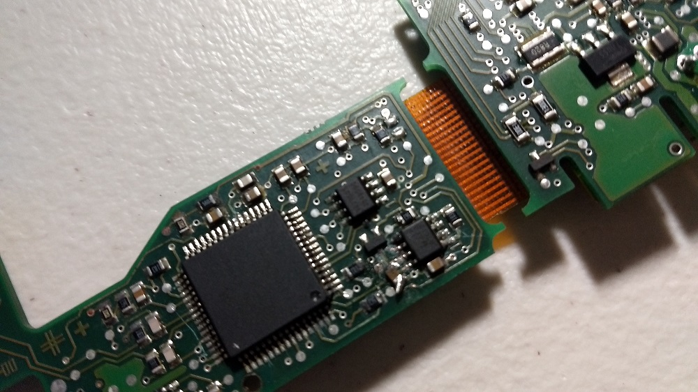
Problem = Purchased a Mercedes clk 320 for $850. That was the first problem. Second being the PCB board underneath the shiftier/gear selector that tells the trans controller what gear it is in etc. has made its maker. The actual potentiometer that reads the gear selector is functioning as it should. The problem I believe by mapping the board best I could, is with the SN65HVD230 CAN Bus Module Comm Module. Also there was corrosion damage to 4 of the 8 pins. Everything else seemed fine. So I purchaced a KNARCO SN65HVD230 CAN chip along with a CHENBO TM Smart Electronics MCP2515 CAN BUS Module TJA1050 Receiver Development Board and CAN-BUS Shield.
Solution = can I or would it be possible to
a) solder the new chip to the bad chip original location. Being that is the only problem. Or does the old chip hold a code memory similar to eprom or bios that I would have read and flash to the new chip?
b) is it possible to take the data from the Potentiometer directly via analog(read) and feed it through the new chip? Then relay the data off the new chip to the trans control unit, or tap it back into the board? (same as (a) I guess, just an off board since the chip I bought is already soldered to a break-out.
c) Is there any other way around this, so I don't have to spend as much as i did on the entire car, to fix this problem?
I was able to read data from the gear selector potentiometer using the code below. As it was close enough to give me an idea if it worked or not, and to get a better look at what pin was for what. I am new to Arduino, still in the learning curve.
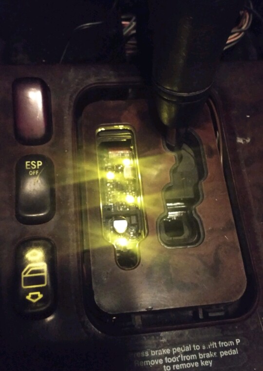
So the short of it I am asking those who have coded Arduino using any CAN-BUS type hardware to help me write a program to make this car shift its gears/or actually to just tell the trans unit what position the automatic shifter lever is at i.e P, R, N, D ![]()
If someone can point me in the right direction I would be more than thankful.
Code that worked as a quick visual to the analog of the gear changer position
int sensorPin = A0; // the pin that the sensor is connected to
int voltagePin1 = A1; // pin connected to voltage divider
float voltage1;       // variable to store voltage value
int voltagePin2 = A2; // pin connected to voltage divider
float voltage2;       // variable to store voltage value

// YOUR calibration
float offset = 513.0; // zeroing bi-directional sensor
float span = 0.05883; // span

const byte numReadings = 32; // number of readings for smoothing (max 64)
int readings[numReadings]; // raw A/D readings
byte index = 0; // index of the current reading
unsigned int total = 0; // running total
float current; // resulting current

#include <LiquidCrystal.h>
#include <Wire.h>

const int rs = 12, en = 11, d4 = 5, d5 = 4, d6 = 3, d7 = 2;
LiquidCrystal lcd(rs, en, d4, d5, d6, d7);

void setup() {
 lcd.begin(16, 2);
  lcd.clear();
Serial.begin(115200); // ***set serial monitor to this value***
for (index = 0; index < numReadings; index++) { // fast-fill the array at startup
  readings[index] = analogRead(sensorPin);
  total = total + readings[index];
}
index = 0; // reset index
}

void loop() {
total = total - readings[index]; // subtract the last reading
readings[index] = analogRead(sensorPin); // one unused reading to clear any ghost charge
readings[index] = analogRead(sensorPin); // read the sensor
total = total + readings[index]; // add the reading to the total
index = index + 1; // advance to the next position in the array
if (index >= numReadings) // if we're at the end of the array
  index = 0; // wrap around to the beginning

// convert value to current
current = (total / numReadings - offset) * span; // value to current conversion

// volt
voltage1 = analogRead(voltagePin1);  // Read voltagePin1
voltage1 = (voltage1*15.45)/1024.0;   // calculates actual voltage

voltage2 = analogRead(voltagePin2);  // Read voltagePin2
voltage2 = (voltage2*15.45)/1024.0;   // calculates actual voltage

// print to serial monitor
Serial.print("Current is ");
Serial.print(current); // default two decimal places | ...(current, 1);  is one decimal place
Serial.print(" Amp   "); // CHANGED to Serial.print
Serial.print("BatteryVoltage is ");
Serial.print(voltage1);
Serial.print(" Volts    ");
Serial.print("SunVoltage is ");
Serial.print(voltage2);
Serial.println(" Volts     ");  // end of line

lcd.setCursor(0, 0);
lcd.print(current);
lcd.setCursor(0, 1);
lcd.print(voltage1);
lcd.setCursor(0, 2);
lcd.print(voltage2);

}