Hi guys,
what H-bridge do you recommend me for a motor 250W 24V 14A to the PWM modulation of velocity that it can connect to Arduino? Thanks in advance.
Hi baldursgate,
What do you want to move with this? A lifesize-model of a steam locomotive?
The voltage isn't a problem but the high amount of current you want to pump through this.
Maybe you should use the shield to control high-power transistors which can bear the power.
Do you also want to change the motor's speed?
If so the transistors also need to have a high reaction time or else the they won't be fast enough for the PWM's fluctuation time.
If this is for the bicycle you talked about in your other thread you might not need a full H-bridge.
Do you need reverse?
That's not a full motor specification - please give the datasheet if possible, part number, website,
whatever it takes to actually know what you have.
Yes this is the website >> 24 Volt 250 Watt Brushed Electric Motor With 25h Sprocket 24v 250w | Acquisti Online su eBay
Really I am realizing this project:

I want control the velocity of motor to vary of the skate inclination. I read the inclination value with a gyroscope. I must use a driver suitable for this motor that it allows me to adjust the speed in PWM.
Sorry if I'm vague.
Are you wanting to buy a motor shield or want to build a h- bridge?
Something like this should work.
https://www.dimensionengineering.com/products/syren25
There are a billion cheap motor drivers on ebay but you get what you pay for sometimes.
Its more fun and challenging to build your own though.
Or this paralleled (both channels drive one motor in parallel): Pololu Dual VNH5019 Motor Driver Shield for Arduino
Yes @alka, you're right but I haven't got enough knowledge to build one. However I have seen some sites that explain how I can do and I think that if I build my own driver I save my money and I learn at the same time. I have seen that to realize a H-bridge are required some transistors that must withstand a current of 14A for not counting the inrush current of the motor. What transistors do you recommend me?
I have found this circuit that it allows to change the direction of the motor and adjust the speed in PWM >> Pilotare un motore DC tramite un ponte ad H utilizzando Arduino UNO
It is very simple but it don't give me info for the resistors and diodes that he use.
This will get you started on the right path. More Power MOSFET H-Bridge Circuit Examples. It gives you the schematic for a h - bridge using power mosfets and bi polar junction transistors to control it. The two 2n222 are bi polar npn transistors. You will need N-channel MOSFET IRF630, and P-channel MOSFET IRF9630. It explains how everything goes together, if you go to the link. See how you get on and if you more questions just post them here.
Both of those circuits will have a problem with shoot-through where both gates are momentarily on. I would not recommend either of those.
This is whole new can of worms.
Also you need 24 volts. Neither of those bridges are suitable for that voltage.
The irf9630 will handle about 1.5-2 amps MAX. And it will be a toaster around 2 amps.
You will need mosfets with a RDS On of 0.004 Ohms or less or go with multiple parallel mosfets.
If you really want a schematic for a discrete bridge that will handle that voltage and current I can probably muster one up. The amount of components needed will shock you.
There are driver ics that are more suitable for this kind of power like the hip4081
Thank you guys for your help x'D. I believe the only problem is to find the components that support 24V and 14A continuously, right? I don't want build nothing of complicated. I just wanted to know if these components exist, or I can get these results only with more complicated circuits. Another question: is the inrush current of motor an additional problem to choose these components or not?
Leodoggie:
This will get you started on the right path. More Power MOSFET H-Bridge Circuit Examples. It gives you the schematic for a h - bridge using power mosfets and bi polar junction transistors to control it. The two 2n222 are bi polar npn transistors. You will need N-channel MOSFET IRF630, and P-channel MOSFET IRF9630. It explains how everything goes together, if you go to the link. See how you get on and if you more questions just post them here.
That is a bad circuit and has lots of issues including shoot-through (a complete killer at the power levels
you need) - avoid completely. MOSFET H-bridges are done with MOSFET driver chips and all n-FETs.
Checkout any high-low MOSFET driver chip datasheet. For instance IRS2001, HIP4081, FAN7388
I couldn't find any suitable schematics on the net so..
I just put this schematic together... In theory it should work.. Sorry no values are entered in.
Build at your own risk (and let me know if it works).
Don't do it to save money.. I have spent hundreds of dollars over the years building cheap motor drivers.
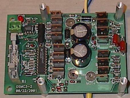
I really like the hip4081, I have made a few scooter sized controllers based around this. Search for OSMC.
One of the premade drivers from polulu or dimension engineering will get you moving with the least frustration.
24volt.pdf (19.2 KB)
Thanks @alka for this circuit but I believe that I will try to build this circuit >> http://www.logicaprogrammabile.it/wp-content/uploads/2012/02/PonteH.png because it is intuitively easier. I am not electronic but an electrotechnical and unfortunately they lack the basics. I will ask to electronic shop if they send transistors suitable for these power levels. if there is news I will let you know. Thank you for your help! ![]()
Yeah, that would do it (you could scale that way back to probably 2 Mosfets per leg for your application).
I put together a prototype using 2 irfb7546 mosfets per leg. Works very nicely can handle up to 40 volts and 20 amps. Cost under 20 dollars to put together.
Circuit is exactly like osmc just with fewer mosfets.

Please don't try and make this one for controlling anything more than about 5 volts and maybe 1/2 and amp.
" http://www.logicaprogrammabile.it/wp-content/uploads/2012/02/PonteH.png because it is intuitively easier"
But by building it for a tiny motor, it will teach you a lot.
The circuit I put up ( although more complicated) is close to the bare minimum to even have a chance of working.