Intervalometer Code (and design!) Submitted for Peer Review

Hi everyone!
I was inspired by some users here to create an intervalometer for my Canon T3i. I have yet to obtain the proper interface cable (3/32" stereo plug), but I did simulate the digital output to the shutter pin using an LED. I will post the schematics soon, but before I do I wanted to fine-tune the code as much as possible.

I am admittedly a newbie with Arduino programming, but I have a strong DIY background with many other languages, so this one wasn't difficult to pick up.

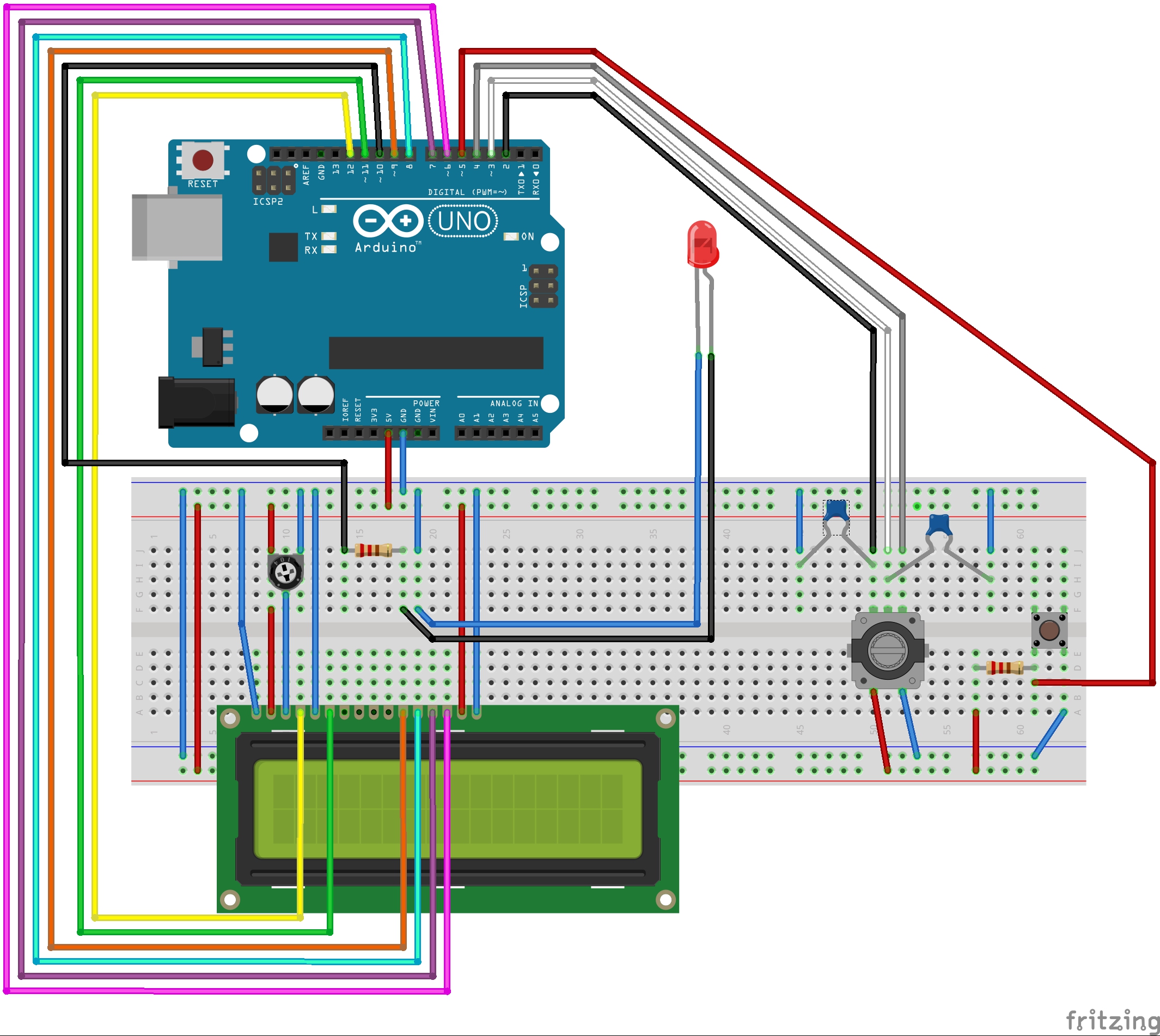
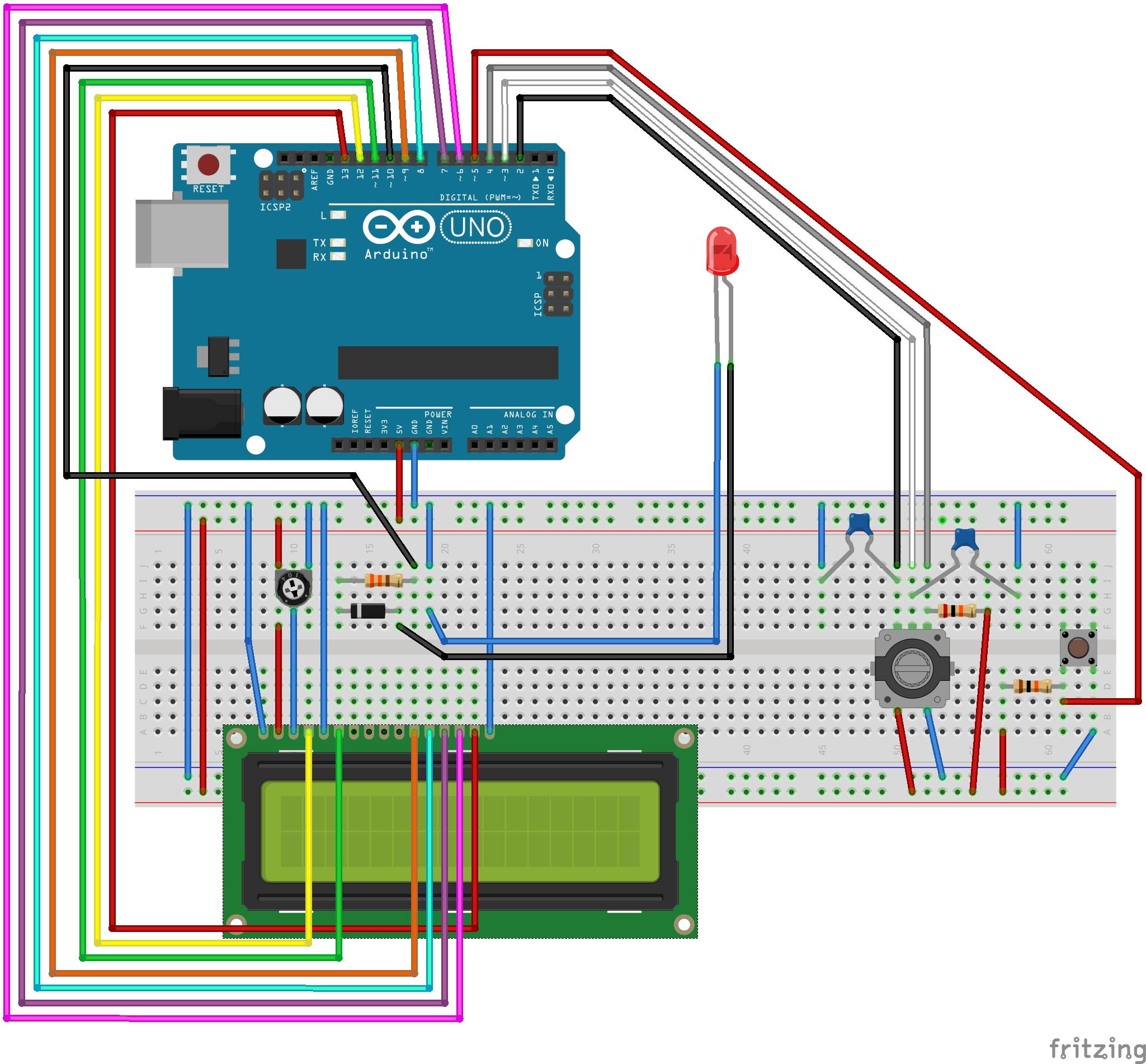
I wanted to make a super simple interface using my 16x2 LCD, a cheap rotary encoder, and a simple push button. I also tossed in an LED, a few resistors, and capacitors and I think I have a working prototype.

I would greatly appreciate it if someone would just give my code the once-over. Let me know if I missed anything major, made any mistakes, or committed any programming taboos. I wrote this from scratch, using only the built-in example codes for the LCD, rotary encoder, and push button. The rest of the code is my best guess at how to approach an intervalometer.

I think my approach is made simpler by the fact that I only care about opening and closing the shutter, and not about focusing. I think this means I can get away with using only the shutter and ground pins, and ignoring the focus pin.

My code is attached. I will update it as I get closer to a final solution, and I will be sure to post the entire build once I am done.

Thanks for your time!
Nate

Intervalometer_v3.ino (11.9 KB)

I have yet to obtain the proper interface cable (3/32" stereo plug),

You may have better luck with the correct designation "2.5mm"

From what I have seen the same plug is labeled both ways depending on the vendor.
Thanks for the heads-up! :slight_smile:

For some reason, clickState is being set to 6 every loop cycle. I can't tell why. Any ideas?

clickState is initialized at 0, and incremented for each time the rotary encoder wheel switch is clicked.

It should not increment unless the switch is clicked.

Scratch that. The code is close but still a little buggy. I am also tweaking some debouncing issues with the rotary encoder and switch. I will post back when I have cleaner code, but I welcome any advice on the existing version!

Happy New Years All!
I am happy to report that I have a working prototype and I am now looking for a suitable enclosure! :slight_smile:

I sketched it up in Fritzing the best that I could. I had to fake the KY040 rotary encoder with another 5 pin encoder, but it is clear enough for the diagram. All the other parts were easy to find in the standard Fritzing library.

Now that the demo is complete, please feel free to whip it up and load the code and let me know what you think!

This is a barely working prototype. I need to fine tune a lot of things. Where do I start?
Thanks again for your time and expertise!
Nate

Intervalometer_v3.ino (12.9 KB)

Parts Used

  • Arduino Uno (Rev3)
  • LCD screen 16x2
  • Rotary Encoder w/ switch
  • Pushbutton
  • Ceramic Capacitor .22uF
  • Ceramic Capacitor .22uF
  • Trimmer Potentiometer 10kΩ
  • 330Ω Resistor
  • 10kΩ Resistor
  • Red (633nm) LED (shutter simulate)

Is this helpful?

Slight modification. I replaced the 330K resistor to the shutter pin with a transistor. This works much better!

(Showing the replaced part.)

Are you familiar with the Magic Lantern Project? I think you'll find that you can achieve everything you want with that, without any extra hardware (except an SD card).

It was actually a spin off from the film industry and offers more features than you can shake a stick at. Even if you still opt to go with the arduino, I think you'll find that magic lantern will offer you more control than you'd have believed possible.

Hi Ken,
I was not familiar with that project. It sounds awesome, thanks for sharing! I may attempt this if I get a backup camera in the future.

For now I want to focus on learning how to build, code and use my new Uno. I was hoping for some feedback on my code and hardware choices.

I am not an electrical engineer, and the parts I have chosen are based on tidbits of other projects. I would like to make sure my resistor and capacitor values are correct, and that I am not missing any key safety components.

Also, is there a way to estimate how long my device will run on a specific battery? (9v, AA, AAA, etc.)

Thanks for your feedback! :slight_smile:
Nate

(I just ordered a host of new components, including an LCD backpack to help simplify the wiring diagram. I am also getting a new enclosure! I will post back once I have upgraded the build.)

I'm not too sure about your transistor switching arrangement. I believe that the canon uses 3.3v logic so needs to be protected from the arduinos 5v. Also there should be a current limiting resistor on the feed to that base transistor. Otherwise, you can potentially damage the arduino.

Here's my suggestion for the interface to the camera shutter input. The diode does the job of protecting the camera from the arduino and the resistor (probably redundant here) is to protect the arduino from having too much current drawn from it's I/O pin.

BTW in this configuration the output from the arduino will be active LOW (ie digitalWrite(10, LOW) will activate the shutter.

canon.JPG

Thanks Ken! That is a great point! I hope I don't (or didn't) damage my camera, as I have been running some test time lapse shots with the recent snowfall. I can see a few ares for improving the battery life. Namely, switching the LCD display backlight off when we start exposing. A brand new 9V is already showing signs of being dead after about 2 hours of shooting. Granted, it is freezing cold out. If I had a hand warmer, the battery might be doing a little better.

So any particular type of diode?

Thanks again!
Nate

KenF:
there should be a current limiting resistor on the feed to that base transistor.

do you suggest keeping my transistor in place along with your diode/resistor arrangement?

nschoonover:
do you suggest keeping my transistor in place along with your diode/resistor arrangement?

No. Personally I think the transistor is redundant.

The resistor is probably also redundant, but I'd leave it there as a bit of bullet proofing.

Fortunately, the pulses you send to set off the shutter are likely very short, so you've probably got away with it thus far. I wouldn't leave it like that on a long term basis though.

What about this setup? Here I have made the changes you suggest for the shutter pin, and I have utilized Digital pin 13 to run the LCD backlight. It does flicker during startup, but once the program is running the controls work well. It shuts off the LCD to conserve battery power during the exposure cycle.

Parts Used:
Arduino Uno (Rev3)
LCD screen 16x2
Rotary Encoder w/ switch
Push button
Diode
Ceramic Capacitor .22uF
Potentiometer 10kΩ
330Ω Resistor
20kΩ Resistor
10kΩ Resistor
LED (shutter simulate)

I also updated the code to reflect these hardware changes. I am eagerly awaiting my LCD backpack which (I hope) will drastically cut down on the number of pins I am using.

As usual, I welcome any comments or feedback. I really, really don't want to ruin my camera. I think this setup is safe, but I would rather be positive! Thanks!
Nate

Intervalometer_v3.ino (13.9 KB)

Can someone tell me why I am using resistors and capacitors for debouncing the rotary encoder/switch? I know that is what they are there for, I just don't understand how the values are chosen.

nschoonover:
I have utilized Digital pin 13 to run the LCD backlight. It does flicker during startup, but once the program is running the controls work well.

Pin 13 is pulsed by the bootloader during startup just to let you know all is well. Naturally this behaviour is having a minor impact on your backlight. You can either just accept it or pick another pin.

nschoonover:
Can someone tell me why I am using resistors and capacitors for debouncing the rotary encoder/switch? I know that is what they are there for, I just don't understand how the values are chosen.

Encoders are just a pair of switches arranged so that they turn on and off at the appropriate moments. All switches have some bounce where the contacts make/break a few times before finally staying on properly. This bouncing is usually over within about 50 microseconds so is un noticeable to the casual obserer. Your uno, however, is fast enough to percieve these bounces as if they are separate events.

As the switch goes from one state to the other, it's output is temporarily counteracted by the charge on the capacitor.

When the switch closes, the current on the output of the switch will be swallowed by the capacitor until it's charged. By that time any bouncing on the contacts will be complete.

When the switch opens, the capacitor will feed the circuit for a moment longer, until it is finally discharged. By this time, the contacts on the switch are now well separated so there will be no further bounce.

The charge/discharge rate of the capacitor will determine how much "debounce" is achieved. As an example, if the capacitor value were too big, your uno wouldn't notice the switch turning on until it has been active for a significant amount of time. In an extreme case, that could be longer than the time the switch is actually active.

The rate of charge/discharge is dictated by the resistor and by the current drawn by the circuit. The research involved in determining these factors and then doing the calculations is more trouble than it's worth when someone else has done the job already. Besides the EXACT amount of debounce is not critical, so if the values look about right, they'll generally work.

Without the hardware debounce your encoder could still be debouned by software within your sketch. A simple (very short) delay whenever a pulse is detected, will do the job fine. So they're not essential, but a nice touch.

Thanks again Ken! :slight_smile:
This is just the concise, informed answer that I was looking for!

I am fine with the flashing for now. Once I clear up some digital pins I can switch it. Do you think I can utilize the analog pins for any of my inputs? (Possibly digital pins 2-5 to analog pins 0-3)? And what would the implications of this change be?

I did start with just a software debounce using a delay of about 20ms. It makes sense that the caps even out the current, creating an effective hardware delay. I wonder, can I remove the caps and use a longer software delay?

I have lots of capacitors, and some may fit the final build better than the current ones. Their values could be significantly different. I am not sure how to understand the range of capacitance values that I could use to achieve the debounce. Does choosing a polarize cap make any difference here?

I can see this debouncing is a whole separate conversation, so I will take up the research aside. If I make any significant changes as a result I will post them to the final build.

Thanks for your help! :slight_smile:
Nate