Automotive PWM control of p-channel MOSFET (IRF4905) as high side switch

I'm working on an automotive project which will use an Arduino as a controller. For this part, the requirements are:

  • use the IRF4905 (PMOSFET, 55V, 740W, .02 ohm RDS(on)) as a high side switch

  • switched load could be up to 150W (preferably without heat sinks on the PMOSFET)

  • EDIT: load is not (very) inductive (mostly LED (arrays), and possibly incandescent and halogen lights)

  • loads to be managed with the Arduino's native 500Hz PWM

  • all components to be through-hole
    Assumptions which can be made for this topic:

  • +V is reliably 11-15V

  • reverse polarity protection is in place
    No assumptions can be made about which PWM values will be used or when (they'll be all over the place).

Without knowing as much as necessary or learning a ton of the calcs required to make complete sense of everything, I've read lots on this (here and elsewhere) and have not been able to find any complete answers. I did a Google search on these forums which produced a lot of topics on this; I've read every one of them and even started my own. Lots of hints, allusions, partial answers, etc. - a lot of it beyond my understanding, and nothing definitive.

Here is a commonly suggested schematic to allow logic level control of PMOSFETs:

02ab_loads_a.gif

However, PMOSFETs won't last very long if the Arduino's 500Hz PWM is applied to them; switching takes too long and they'll overheat. To mitigate this heat production, reductions in switching times are required; here are two discrete-component approaches which I've cobbled together from suggestions and circuits I've found in various places:

It is likely neither one will work as-is. While I appreciate learning more about the hows and whys of doing things these ways, at the moment I just need to get it to work - preferably as efficiently as possible while keeping discrete component count to a dull roar.

What I know so far:

  • Large values of R5r/R3r have a detrimental effect on turn-off times of the PMOSFET. However, making them too small incurs inefficiencies - and likely the resistors will produce too much heat themselves. Once the PMOSFET has been shut off, negligible current is required to keep it there. However, when it's on, most current is routed through this resistor, so heat becomes a concern. I'd be happy to hear of other or additional ways to minimize turn-off times while minimizing heat production from any components.
  • While I have experienced some glimmerings of understanding, I don't know how far off I am with either the "5" or "3" circuits.
  • I don't understand hardly any of "5", and have only partially figured out the push-pull arrangement in "3", so I'm not sure of any of the supporting components in either circuit (missing, in excess, mis-valued, etc.)
    NB I'd be happy to hear of any high side switch, p-channel MOSFET gate driver through-hole IC which would allow the above to be accomplished with minimal (one?!) components.

I'm looking forward to a definite way to reliably use an Arduino's native PWM to manage high current loads via PMOSFETs in an automotive environment.

Cheers!
Dirk

dephwyggl:
I'm working on an automotive project which will use an Arduino as a controller. For this part, the requirements are:

  • use the IRF4905 (PMOSFET, 55V, 740W, .02 ohm RDS(on)) as a high side switch
  • switched load could be up to 150W (preferably without heat sinks on the PMOSFET)
  • loads to be managed with the Arduino's native 500Hz PWM
  • all components to be through-hole

Assumptions which can be made for this topic:

  • +V is reliably 11-15V
  • reverse polarity protection is in place

No assumptions can be made about which PWM values will be used or when (they'll be all over the place).

Without knowing as much as necessary or learning a ton of the calcs required to make complete sense of everything, I've read lots on this (here and elsewhere) and have not been able to find any complete answers. I did a Google search on these forums which produced a lot of topics on this; I've read every one of them and even started my own. Lots of hints, allusions, partial answers, etc. - a lot of it beyond my understanding, and nothing definitive.

Here is a commonly suggested schematic to allow logic level control of PMOSFETs:

02ab_loads_a.gif

However, PMOSFETs won't last very long if the Arduino's 500Hz PWM is applied to them; switching takes too long and they'll overheat. To mitigate this heat production, reductions in switching times are required;

Switching frequency has nothing to do with rise and fall time. The only thing is that the rise and fall time is a fixed value, and multiplied by a faster PWM rate results in the mosfet being in the "bad zone" for longer in total.

Anyway, you don't need an elaborate circuit... the one in your quote is just fine (aside from not showing a proper resistor between the base of the BJT and the PWM pin). If you want a PWM rate slower than 500 Hz, just change the timer divider.

Krupski:
Switching frequency has nothing to do with rise and fall time. The only thing is that the rise and fall time is a fixed value, and multiplied by a faster PWM rate results in the mosfet being in the "bad zone" for longer in total.

I know switching (PWM) frequency is distinct from rise and fall times; the time taken to transition the rise/fall times is what's of concern. A MOSFET will experience them 1000 times per second. The power dissipated because of these transitions is what I'm attempting to mitigate. I have seen comments that the Arduino's PWM frequency of 500Hz (see note below) is too high to manage the power (100-150 watts) I'd like to see switched by the IRF4905. Yours is the first I've seen that says otherwise. (Not saying you're wrong; I'm just getting conflicting information.)

Krupski:
Anyway, you don't need an elaborate circuit... the one in your quote is just fine (aside from not showing a proper resistor between the base of the BJT and the PWM pin). If you want a PWM rate slower than 500 Hz, just change the timer divider.

Simple is good! :slight_smile: Altering the Arduino's 500Hz PWM frequency is not an option for this project. ...and, if anything, I'd like to increase it (2500+ - at which I'm sure the issues I'm trying to clarify here will only be exacerbated).

Thank you for your comments, Krupski.

Cheers!
Dirk

Hi,
What is the load?
Have you looked at purpose made Automotive High Side Switches?

http://www.st.com/en/automotive-analog-power-ics/high-side-switches.html?querycriteria=productId=SC1037

These devices are designed specifically for DC automotive purposes with low RdsON characterisitcs and High Side Switching.

Tom.... :slight_smile:

Most of such devices cannot PWM, they take 100's of us to switch.

We here have the problem that there is only an unclean 12V supply to work with, with spikes and dips,
and standard high-side drivers for n-MOSFETs need clean stable 12V to work with. One approach is
a 12V -> 12V DC-DC converter to power a high-side driver and an n-MOSFET to switch. Most
such drivers rely on bootstrapping so your PWM must never reach 100%, so there's always off-time
for the bootstrap cap to charge.

Some drivers do have an always-on charge-pump though, you'd have to search for the right part.

Mark, Tom, thank you both for your comments.

TomGeorge:
Hi,
What is the load?

Thank you for pointing this out. The load is not (very?) inductive; mostly this is for managing lights (LED (arrays) and possibly incandescents and halogens).

TomGeorge:
Have you looked at purpose made Automotive High Side Switches?

Yes. Most of what you pointed to is either not available in through-hole, or can't carry the current required. There are only two possible options I've discovered so far: infineon's BTS442E2 and IR's IR6224&6. The IR6224 and IR6226 are obsolete. The BTS442E2 is promising, though a bit pricey. I may look at it some time. (This type of solution looks very promising for projects with lower current requirements, though.)

MarkT:
Most of such devices cannot PWM, they take 100's of us to switch.

Thank you for that reminder, Mark. I was not able to figure out the specs well enough to determine if either the BTS442E2 or the IR622X could switch quickly enough for 500Hz. (To my untrained eyes, they did appear to be rather slow.)

MarkT:
We here have the problem that there is only an unclean 12V supply to work with, with spikes and dips,
and standard high-side drivers for n-MOSFETs need clean stable 12V to work with. One approach is
a 12V -> 12V DC-DC converter to power a high-side driver and an n-MOSFET to switch. Most
such drivers rely on bootstrapping so your PWM must never reach 100%, so there's always off-time
for the bootstrap cap to charge.

Some drivers do have an always-on charge-pump though, you'd have to search for the right part.

Let's not worry about power supply cleanliness and assume (for now) that we have clean power at 11-15V.

I have not been able to find any reasonable p-channel drivers, and I've asked before if n-channel drivers can be used to drive PMOSFETs and if so, how. No answers yet. From what I've been able to figure out on my own, n-channel drivers may have switching times of 15-30ns (MAX627, MC34152, TC4427, TPS2812, and probably others), but that's into 1000pF. The IRF4905 gate is - as far as I can tell - closer to 3000pF. Nice thing about these is they frequently come in dual packages (reducing parts count is always good :slight_smile: ).

Would either of you be willing to review my "5" and "3" circuits above and provide feedback on which might be preferable and what either or both may need to be viable?

Cheers!
Dirk

Why not try N-channel MOSFETs and switch the low side to Gnd?

Really low Rds; can drive from Arduino direct; rise & fall time in the nanoseconds; thruhole.

CrossRoads:
Why not try N-channel MOSFETs and switch the low side to Gnd?

Switching is not available on the low side; high side only.

Cheers!
Dirk

In a different topic, MarkT suggested an n-channel solution using the MIC4421/2. I've taken another look at this; the MIC4421/2 can drive 47,000pF with a rise/fall time of 25ns at 9A! While it's described as a "Low-Side MOSFET Driver", could it be used to drive a p-channel MOSFET on the high side? (It's a tad pricey, but if this becomes a 2-chip solution... :slight_smile: )

Cheers!
Dirk

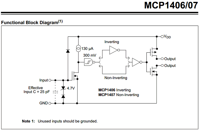
While perusing some other, related things, I think I've found something more appropriate than the MIC4422; Microchip's MCP1406/7 ("High-Speed Power MOSFET Drivers" - no mention of "low" or "high" side). It can drive 6,800pF in 40ns at 6A. ...and is significantly cheaper. I've asked before if an n-channel MOSFET driver can be used on a p-channel MOSFET as a high side switch. The MCP1406/7's spec sheet includes the diagram:

MCP1406-07_func_diag.gif

From what I can tell, the output of this driver could be used to manage any typical power MOSFET's gate pretty quickly (i.e. the IRF4905's at 3,300pF). Comments?

Cheers!
Dirk

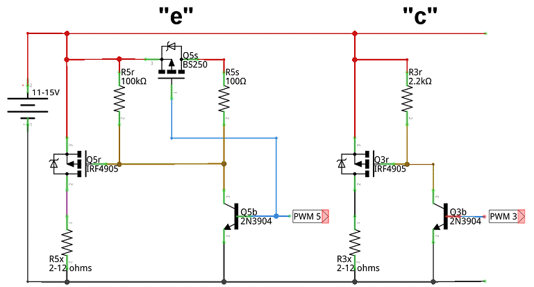
I've been thinking some more (uh oh) on how to speed up p-channel MOSFET switching times. Specifically, speeding up switching a PMOSFET off. Shutting it off is done via a pull-up resistor, and it seems that generally, the lower the resistance, the faster the PMOSFET will shut off. This has consequences though; when the PMOSFET is on, all current through the resistor is shunted to ground - which produces more current than wanted via that route, so I thought maybe increasing the resistance when the PMOSFET is on, and decreasing it when it's off would mitigate that.

The following shows the conventional way to pull-up a PMOSFET's gate in "c", and a (theoretical) way to speed it up and mitigate wasted power in "e":

I'm aware that the specified components may not be optimal and there are likely support components missing, but this is just to see if this could work in theory. (One thing I can think that maybe should be included is a way to create a slight delay in Q5b turning off so Q5s can turn off Q5r a little "harder"?)

Comments?

Cheers!
Dirk

Lots of interesting stuff there. That's why most people just use packaged solutions.

Commenting on variation "e" directly above: it's difficult to control Q5s. When the main transistor is off, its gate must be about 12V, so the source of Q5s is about 12V and Vgs now is going to be negative - the transistor is driven on hard. Yes you want this, but how do you switch it off? You will have to draw a LOT of current through Q5b before you can get Q5s down to a voltage where you can switch it off.

If you want to turn the P-MOSFET off fast, you need a voltage greater than its drain: greater than the supply. A simple voltage doubler circruit can be built to pump up a small capacitor to about 24V, then that can be dumped into the P MOSFET with an N-type at the appropriate time.

MorganS:
Lots of interesting stuff there. That's why most people just use packaged solutions.

...and you just contributed a bunch more. :smiley:

MorganS:
Commenting on variation "e" directly above: it's difficult to control Q5s. When the main transistor is off, its gate must be about 12V, so the source of Q5s is about 12V and Vgs now is going to be negative - the transistor is driven on hard. Yes you want this, but how do you switch it off? You will have to draw a LOT of current through Q5b before you can get Q5s down to a voltage where you can switch it off.

If you want to turn the P-MOSFET off fast, you need a voltage greater than its drain: greater than the supply. A simple voltage doubler circruit can be built to pump up a small capacitor to about 24V, then that can be dumped into the P MOSFET with an N-type at the appropriate time.

These types of comments are exactly what I'm looking for, Morgan. Thank you. :slight_smile: I suspected there would be issues with shutting Q5s off, but wasn't sure what or why. I needed some way to invert Q5b, and a PMOSFET came to mind. (I appear to have PMOSFETs on the brain. :o )

I'm not sure I follow your logic. I'll try to explain mine and see if perhaps they're the same. There are two stable states in "e":

  • Q5b is off and Q5s is on (Q5r is off); this is the "default" state of the circuit

  • Q5b is on and Q5s is off (Q5r is on)
    The purpose of Q5s is to ensure:

  • When Q5b is off, current flows through R5s

  • When Q5b is on, current flows through R5r
    I realize there are transitions while the above conditions swap, but is speed an issue here? (My earlier mention of shutting off "hard" was directed at Q5r, not Q5b or Q5s.) Maybe because we want to switch in the lower resistance (R5s) so Q5r can be shut off as quickly as possible.?.?.?

I think the idea of swapping resistances depending on the state of Q5r (and Q5b) is workable; I just don't know enough and this was (to some degree) a shot in the dark. ...er, pun not intended. :stuck_out_tongue: I'm not sure this would be applicable, but I've seen stuff with paired diodes and different valued resistors.?.?.? Some other way? The goal is to remove R5s as a path to ground or increase its resistance (which would not be speed-sensitive) when Q5r is on. Hmmm...

Again, this idea may not be practicable, but it allows me to understand useful ways to manage various aspects of circuits (like voltage dividers, RC calcs, etc.) I'm still hopeful to be able to use an n-channel MOSFET gate driver as asked in earlier posts here, here and particularly here. :wink:

Cheers!
Dirk

I've done some more thinking, and have come up with something else; no idea if it'd work, but what the heck, throw it out there and see what sticks. :stuck_out_tongue:

In "e2":

  • When Q5a and Q5b are off, Q5s is on (Q5r is off) (PWM is low; default state)
  • When Q5a and Q5b are on, Q5s is off (Q5r is on) (PWM is high)
    I'm thinking I may have something fundamentally wrong.?.?.?

Cheers!
Dirk

I've come up with a couple of other ways to speed up turning off Q5r, but they were tending to get more complex than I'd like. After a bit more stumbling around in the interwebs and learning tons more, I've come up with a simpler solution (he says hopefully). The goal at the moment is to minimize R5r (as much as Q5r will allow; its value was selected to drive about 2A into Q5r's gate) when Q5r is to be off, and when we want Q5r on, maximize the efficiency of the path to ground. So, I came up with (again, "c" is a "common" approach and "e3" is my latest incarnation):

I've also (tentatively) added in D5s and R5s. Q5r has most everything spec'd at a VGS of 10V, so I thought if we can keep the maximum voltage at the gate to something resembling that, it should be easier to drive it back to ground when we want it back on. So, D5s is there to limit voltage at the gate to 10V, and R5s is there to ensure it doesn't release too much magic smoke (the shown value should keep it to around 0.5 watts).

I'm still thinking about how to speed up turning Q5r back on. If limiting the voltage swing to turn it off works, maybe limiting the voltage swing to turn it back on would also work. :slight_smile: So, limit the lower voltage to something that will turn it on completely, and minimize the voltage swing necessary to shut it back off - maybe 1.5V (something well below VGS(th)). Perhaps a voltage divider which selects resistance to ground - likely through an "inverted" Q5b...

Comments?

Cheers!
Dirk

Hi all,

Can an n-channel MOSFET driver be used to drive a p-channel MOSFET?

I have searched for a through-hole solution (preferably in a TO-220 like package) and have found only "low side" (n-channel) solutions. With one exception: the MCP1406/7 (documented as "6A High-Speed Power MOSFET Drivers" with no mention of high or low side). My current level of knowledge is insufficient to determine whether or not this is usable with PMOSFETs in a high-side switching role.

I am also searching for any mention of using the MCP1406/7 with any p-channel MOSFET. I found exactly one mention of doing this, but that aspect was ignored with comments about other issues in the proposed schematic.

Dirk

What are you actually trying to do? Are you trying to dim lamps using PWM?

NOSUM:
What are you actually trying to do? Are you trying to dim lamps using PWM?

Yes. See my first post.

I have been doing a bit more digging and it seems I'll be using a discreet solution:

  • I have not been able to determine if n-channel drivers can be used with p-channel MOSFETs;
  • The n-channel drivers I've found are about 10 times slower than I thought;
  • The few integrated high-side switches I found appear to be too slow for the PWM rates which I'll be using.
    Also, I was mistaken about the Arduino's PWM rate; its default rate varies depending on which pin you use, and the 500Hz is not correct for any pin. I've decided to go with pins 5 and 6 which have a default rate of 980Hz. Depending on how well driving the big MOSFETs go, (I want to be able to run them without a heat sink), I'll be bumping this up - maybe to 2500Hz.

Here is the latest I've come up with:

  • R3/R4 limit voltage thru Q1 to 3.5-4.8V;
  • R5 and R6 limit current to about 100mA through Q2 and Q3 respectively;
  • When Q2 and Q3 "short", current to ground is limited to about 50mA.
    I'd like to see much more current to the gate on Q4, so am thinking about subbing in 2A BJTs for the Q2/Q3 pair (maybe MPS750/650) and adjusting R5 and R6 so Q4 will see about 1A at its gate.

I appear to not be up to the challenge of calculating the resulting rise/fall times of Q4 and what kind of temperatures it may be seeing at 980 - or 2500 - Hz.

Help, feedback, corrections, comments are all appreciated.

Cheers!
Dirk

Automotive transients easily exceed the 20V gate-source rating of the IRF4905. For reliability, include a 15-20V zener across the P-fet's g-s.
I like the BMS3003 for a high-side mosfet, it has built-in g-s zener but no d-s zener.

Careful that during cranking, you can have only ~6V gate-drive available and some mosfets will cook and die then because they are partially on.

If you are trying for 2A of gate drive, that is nsec switching times which makes alot of EMI and noise. You want fast switching to minimize the mosfet's time spent in the linear region, but not too fast.
A gate series resistor of around 47R slows it down a tiny bit.

"e3" is not quite good, R5t is huge and so Q5b cannot pull much current and very slow turn on of Q5r. R5t best deleted. R5r is really too small and makes alot of heat.
For fast-switching the mosfet, "c" is the simplest and R3r could be even lower say, a 1/2W part 1k.

Thank you for your conbtributions, prairiemystic.

prairiemystic:
Automotive transients easily exceed the 20V gate-source rating of the IRF4905. Automotive transients easily exceed the 20V gate-source rating of the IRF4905. For reliability, include a 15-20V zener across the P-fet's g-s.
[...]
Careful that during cranking, you can have only ~6V gate-drive available and some mosfets will cook and die then because they are partially on.

As mentioned in my first post, we can assume power is reasonably clean for this stage. ...though, I am working on power management (bi-directional TVS/cap/reversed p-channel). If the results are marginal, I'll add an 18V zener across G-S. Also, the IRF4905 has a VGS(th) of 4V (max), so low voltage shouldn't be a (huge?) problem, but I'm looking into a low parts count way to have the system shut off completely below about 10V.

prairiemystic:
I like the BMS3003 for a high-side mosfet, it has built-in g-s zener but no d-s zener.

Thanks! Haven't run across this one yet. I noticed it has a rather high Ciss (13200pF vs 3400pF for the IRF4905). My preference at the moment is the AOTF4185; around 2800pF and rise/fall times less than a third that of the IRF4905. I'm hoping to be able to simply sub them in once I find a reasonable source.

prairiemystic:
"e3" is not quite good, R5t is huge and so Q5b cannot pull much current and very slow turn on of Q5r. R5t best deleted. R5r is really too small and makes alot of heat.
For fast-switching the mosfet, "c" is the simplest and R3r could be even lower say, a 1/2W part 1k.

I was including "c" only for comparison (it wastes too much power) and I eventually figured out why "e" wouldn't work. Thank you for your feedback though; helps me to understand things a little better. I'm in the process of trying to determine if my latest iteration is workable.

prairiemystic:
If you are trying for 2A of gate drive, that is nsec switching times which makes alot of EMI and noise. You want fast switching to minimize the mosfet's time spent in the linear region, but not too fast.
A gate series resistor of around 47R slows it down a tiny bit.

My goal is to be able to PWM at 2500Hz (at variable durations) without requiring a heat sink. 980Hz is workable. I was hoping the 2N3906/2N3904 pair would get me there, but if not, maybe a 1A gate drive (50% of 2A BJTs' capability) might. If I can get to that with the IRF4905, great! If it doesn't, hopefully the same approach would get me there if I sub in the AOTF4185.

I'm lost on how to calculate the actual transition times and how how they translate into temps at the MOSFET. I have no idea (yet) how much current I need at the IRF4905's gate to switch quickly enough to run at 980Hz (ideally 2500Hz) without requiring a heat sink. Ideas?

NB I have thought about maybe switching too quickly, but suspect I'm not there yet. I have noticed comments regarding the possibility of ringing on a MOSFET's gate. Would moving R5/R6 to the collector/emitter of Q2/Q3 respectively help (instead of adding another resistor)?

Again, thank you for all your comments, prairiemystic. Looking forward to more.

Cheers!
Dirk