Hi Guys,
I recently received a new big stepper motor (Model: Y07-58D1-17152) from China.
Now I am trying to collect proper devices to run this motor using Arduino.
I am not someone who has a lot of experience with stepper motor. Saying that, I prefer this driver over the other.
Which one should I purchase? Is there any cheaper alternative?
For power supply, I am thinking about this (36V 10A) ?
Earlier, I tried A4988 driver with power supply of 15V 12A (I can read this on the label, I didn't measure the current though) at maximum 2A setting. It hardly moved the motor.
I retried after around 15 min. The moment I turned on the power, A4988 got fried (saw the little fire beneath the pot).
Either of the drivers in the Original Post should be suitable. The motor seems to require 2.2A and the drivers can provide considerably more, for a nice safety margin. Also, both will work with a 36v power supply.
If you only want to power one motor then you will not need a 10 amp power supply - but lower amperages may not give much of saving.
...R
PS your Reply#1 came while I was composing this. I don't plan to investigate every possible option for you. - sorry, I'm lazy
Thanks Robin,
I thought motor required 3A/phase. Where did you see 2.2A?
These two drivers are relatively very cheaper (I posted them here too).
Are these fine enough as well?
Yes you are correct, the price difference betweem lower current rating (above 5A) is minor.
Also, I don't understand why supplier says this:
When the driving card is raised, it must be lower than the motor required current (otherwise, it will burn the motor) and the motor current is on the motor parameters.
Lower current rating than motor can draw would result in lower torque.
I don't get this.
Thanks Robin.
They have 2 different numbers. On the motor itself, it says 3A.
I will be very thankful if you could give a look into this .
I will then place order.
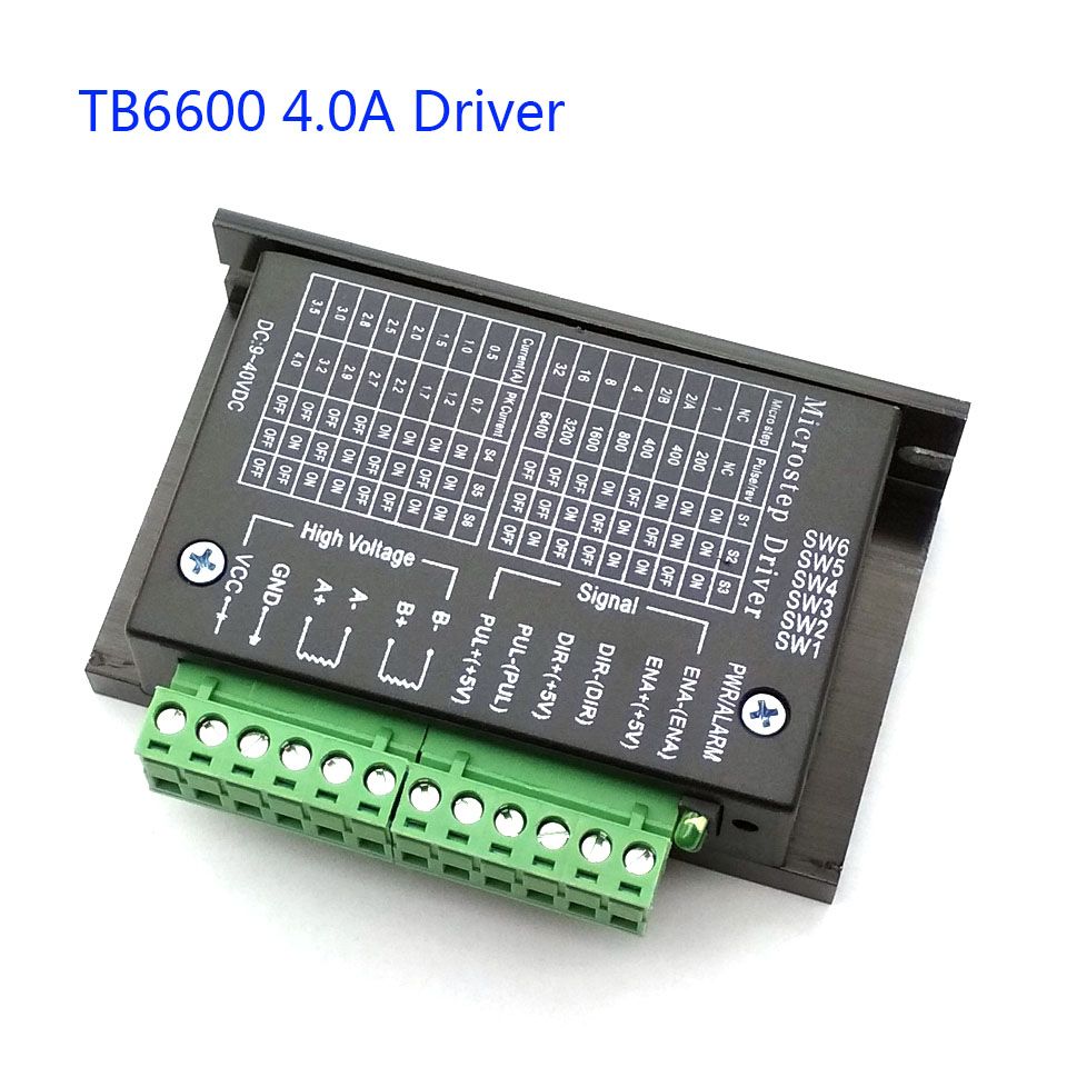
If the amp setting of the driver has to be lower than 3A, then I guess I go with 2.8A current setting (image attached).
On eBay it says TB6600 supports upto 4A motor.. but can't really trust these sellers.. and this is why asking in here is always useful. I am worried about the motor, not the driver.. Unsuitable might fry the motor, what do you say?
I order it though and ST-M5045 which you saw earlier.
I will get back to this thread with some results.
Thanks to Rabin once again.
Robin2:
I have no idea if a TB6600 driver can work with a 3 amp motor. At the price it may be worth the risk.
...R
Hi Robin,
How are you doing?
My TB6600 driver arrived finally!
Surprisingly it can rotate the motor.
Currently DIP switch setting is for 6400 Pulse/Rev.
Test code which works: (Taken from here)
Thanks Robin,
Just to add, test code I pasted earlier only works when DIP switches are set for microstep 32.
Same code doesn't work if the microstep is different than 32.
I tried microstep 1 with:
for (int i=0; i<200; i++)
Code didn't work.
I can't seem to understand the reason.
Robin2:
You need to post the exact code that you uploaded to your Arduino so I can compare it with your code that works.
My code does not write to the Enable pin - for many drivers it is not necessary. Maybe it is for the one you have.
...R
Alright, after I posted my last reply, I tried to set micro step to 1 and slightly modified your code: (snippet where I made changes)
byte directionPin = 5;
byte stepPin = 6;
int numberOfSteps = 100;
byte ledPin = 13;
int pulseWidthMicros = 200;  // microseconds
int millisbetweenSteps = 20; // milliseconds - or try 1000 for slower steps
This code moved the motor but certainly had some jitter.
Please suggest how can I smoothly rotate this motor.
Just to add, similar to my previous project, I would like to add 4 buttons (FWD, REV, EN/DIS & REST), POT for speed control and also control through serial.
Robin2:
You are making it very difficult (and time wasting) when you won't post the complete program like I requested in Reply #9
Like I said I didn't make any changes apart from the snippet I posted.
Anyways here is the code:
// testing a stepper motor with a Pololu A4988 driver board or equivalent
// on an Uno the onboard led will flash with each step
// this version uses delay() to manage timing

byte directionPin = 9;
byte stepPin = 8;
int numberOfSteps = 100;
byte ledPin = 13;
int pulseWidthMicros = 200;  // microseconds
int millisbetweenSteps = 20; // milliseconds - or try 1000 for slower steps


void setup() {

  Serial.begin(9600);
  Serial.println("Starting StepperTest");
  digitalWrite(ledPin, LOW);

  delay(2000);

  pinMode(directionPin, OUTPUT);
  pinMode(stepPin, OUTPUT);
  pinMode(ledPin, OUTPUT);


  digitalWrite(directionPin, HIGH);
  for(int n = 0; n < numberOfSteps; n++) {
    digitalWrite(stepPin, HIGH);
    delayMicroseconds(pulseWidthMicros); // this line is probably unnecessary
    digitalWrite(stepPin, LOW);

    delay(millisbetweenSteps);

    digitalWrite(ledPin, !digitalRead(ledPin));
  }

  delay(3000);


  digitalWrite(directionPin, LOW);
  for(int n = 0; n < numberOfSteps; n++) {
    digitalWrite(stepPin, HIGH);
    // delayMicroseconds(pulseWidthMicros); // probably not needed
    digitalWrite(stepPin, LOW);

    delay(millisbetweenSteps);

    digitalWrite(ledPin, !digitalRead(ledPin));
  }
}

void loop() {
}
What DIP switch setting should I apply for your code?
Robin2:
Try making the motor move at a very slow speed - say 500 millis between steps
There should be no need for a long pulse width - the TB6600 datasheet says the minimum pulse requirement is 2.2µsecs so I would just use 10µsecs.
...R
I will test these changes in the evening and update you.
Robin2:
That is completely illogical. What did you hope to achieve with that?
I see what you mean but these numbers came from testing the code.I was changing number to make the motor run smoothly, which I eventually saw.
Using both parameters you have in your code:
int pulseWidthMicros = 20;  // microseconds
int millisbetweenSteps = 250; // milliseconds - or try 1000 for slower steps
zeus2kx:
Using both parameters you have in your code:
int pulseWidthMicros = 20;  // microseconds
int millisbetweenSteps = 250; // milliseconds - or try 1000 for slower steps
I wasn't able to move the motor.
I can't understand why the changes you made improved matters.
You made two changes. Which of them was the important one?
When you are trying to debug a problem NEVER change more than 1 thing at a time.
I have just noticed (prompted by @outsider's question) that the code in Reply #8 uses pins 5 and 6 whereas the code in Reply #12 uses pins 9 and 8. Both can't be right unless you have been messing with the wiring.
Exactly like this.
Only the pins are different.
Code on this page works but ONLY when DIP switches are set to 1/32th.
If I change the DIP settings, I hear tones.
