PWM long led strip, flickering on low duty cycle

Hello everyone,

thank you in advance for taking the time to read and answer my question. Mainly I am a forum lurker, not a contributor. I have experience in electrics, less so in programming. But I can`t seem to find the correct solution to my problem, so I have decided to ask it here.

The project:

I have 14 meters of 24V led strip dimmable through arduino. The led strips are being fed halfway at both sides ( so at 7 meters) which is enough.
Led strip specs: 18W/m, 24V, CV.


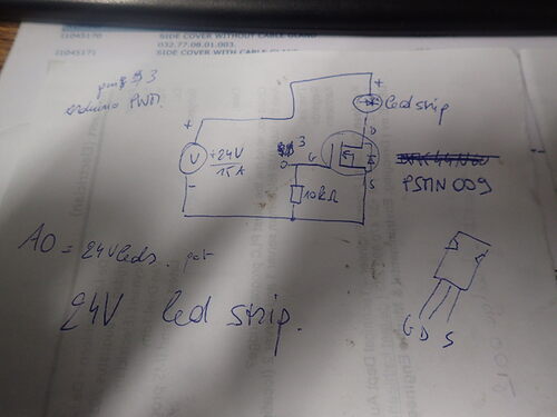
Schematic:


note: the mosfet is capable of handling 5V TTL logic to switch. The led strips are CV, and have resistors built in. So the load on the mosfet isnt drawed correctly, it includes resistors.

The code:

/*
  Analog Input

  Demonstrates analog input by reading an analog sensor on analog pin 0 and
  turning on and off a light emitting diode(LED) connected to digital pin 13.
  The amount of time the LED will be on and off depends on the value obtained
  by analogRead().

  The circuit:
  - potentiometer
    center pin of the potentiometer to the analog input 0
    one side pin (either one) to ground
    the other side pin to +5V
  - LED
    anode (long leg) attached to digital output 13
    cathode (short leg) attached to ground

  - Note: because most Arduinos have a built-in LED attached to pin 13 on the
    board, the LED is optional.

  created by David Cuartielles
  modified 30 Aug 2011
  By Tom Igoe

  This example code is in the public domain.

  http://www.arduino.cc/en/Tutorial/AnalogInput
*/
#include <ResponsiveAnalogRead.h>

int sensorPin = A0;    // select the input pin for the potentiometer
int ledPin = 3;      // select the pin for the LED
int datapin = 6;
int sensorValue = 0;  // variable to store the value coming from the sensor
int PWMled = 0;


ResponsiveAnalogRead analog(sensorPin, true);

void setup() {
  
TCCR2B = TCCR2B & B11111000 | B00000110;
// declare the ledPin as an OUTPUT:
  pinMode(ledPin, OUTPUT);
  pinMode(datapin, OUTPUT);

      bitSet(TCCR1B, WGM12);


}

void loop() {
analog.update();
  // turn the ledPin on

PWMled = map(analog.getValue(), 0 , 1023, 0, 200);

analogWrite(ledPin, PWMled);
datapin = 0;

}

note: simple circuit, reading an analogvalue and stabilising it with a library that uses an algorythm, then mapping it to the PWM output. No problem here.

  • I am using a PC power supply with stable 5V for the arduino, but also for pixelleds also present (whom need alot of current, hence the PC power supply). The power supply is stable.
  • I am using a separate 24V phoenix contact power supply capable of giving up to 10A. In the code the max PWM is 200 (instead of 255) and even this is too bright even for the room ( :slight_smile: slight overkill ). This draws about 6A.

My problem:
First of all, this circuit works. It does what it should, it sends PWM to the led strip, I can dim it.
My problem is, that it flickers alot. Due to my overkill, I am dimming it alot, with very low duty cycles.


These are scope measurements on the gate and the output. Gate switches on 5V (channel B), output is 24V (channel A). The top measurement shows the led strips on minimum PWM, where they flicker alot.
Flickering is visible as 50-60Hz somewhere, although not sure of that. It becomes alot less visible with higher PWM, but is still present.

I realise there is a minimum duty cycle for the leds. This can be configured in the project when necessary, I am not talking about this ( the min PWM moment is shortly visible in the video).

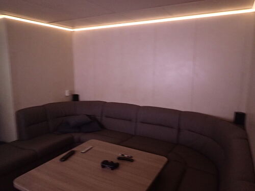
video from the led lighting

What have I tried:

  • playing with the frequency of the PWM. I tried upping it, but it only increased the flickering. Upon lowering, strangely enough it diminishes..
  • online I see all buck circuitry have coils and extra diodes. yet these are usually only designed for up to 1 Amps. putting a series coil through a circuit that draws 8 amps... well, havent got such a coil laying around. And a simple circuit suddenly becomes complex. Then I would need a premade board etc, and those are hard to find. The LM3421 is capable of doing this, but I would need to design and calculate everything myself as no pre made stuff exists for this kind of currents..

What I havent tried:

  • adding capacitors. This would require adding a diode over the mosfet to protect it, and probably make the leds brighter. Might this work to smoothen the flickering?
  • interference problem?

I think this is a current problem. My voltage is a good PWM, but the current isnt constant and enough for the led strips.

Does anyone have any suggestions? I am thinking of remaking it with a constant voltage, but this has its inherent drawbacks as well...

Thank you very much in advance!

krullebolle

AnalogInput.ino (1.49 KB)
Not a problem being a forum lurker. You made a damn good start post!

First off, don't add capacitors. That would effectively drive the leds with a voltage and driving leds with a voltage is terrible non-lineair.

Other thing, there is no such thing as "higher PWM". You can have a higher PWM frequency or a higher PWM duty cycle.

Looking at the screen shots (he, I know that meter). I see a PWM frequency of around 125Hz if I'm not mistaken. (Don't like the interface...). Didn't check it against the register settings in your code. But that is indeed a very very low frequency. The default of pin 3 is 490Hz. And even that is way to low for my taste... But first try the default value. That should look better already.

Other thing, I can't really see two channels in the screen shots. Again, the interface. But higher frequency might give you trouble driving the MOSFET (aka, make it switch slow) but I'm unable to see that from these images.

septillion:
Not a problem being a forum lurker. You made a damn good start post!

Other thing, there is no such thing as "higher PWM". You can have a higher PWM frequency or a higher PWM duty cycle.

Im sorry, bad phrasing from me. I have tried raising the PWM frequency with TCCR2B = TCCR2B & B11111000 | B00000110; ` in my code.

With higher frequencies, the flickering increases instead of decreases.

The duty cycle is done with a potmeter reading, Analogin. In the scope measurements my frequency is the same (lower then Arduino standard, because less flickering then), but duty cycle is different due to different potmeter settings.

The scope is indeed a golden oldie XD

krullebolle:
Im sorry, bad phrasing from me. I have tried raising the PWM frequency with TCCR2B = TCCR2B & B11111000 | B00000110; ` in my code.

That does not raise the PWM, that decreases it! It increases the prescaler to 256 thus setting the PWM frequency t 122Hz...

So I'm starting to think I know the answer to my next question...

krullebolle:
With higher frequencies, the flickering increases instead of decreases.

Did you check this :wink:

Try

TCCR2B = (TCCR2B & 0b11111000) | 0x02;

Which decreases the prescaler to 8 thus increasing the frequency to +- 4kHz. You could also try 0x01 (+-32Hz) but that might be to fast for the mosfet (without driver).

krullebolle:
The scope is indeed a golden oldie XD

I know, we have some at display at my work because we designed it :wink:

septillion:
That does not raise the PWM, that decreases it! It increases the prescaler to 256 thus setting the PWM frequency t 122Hz...

So I'm starting to think I know the answer to my next question...Did you check this :wink:

I did! It increases the flickering notably, but will try to take scope pics tomorrow and upload from the higher frequency. The lower freq. was in the code because this seems to be the best setting as of now... for some obscure reason.

septillion:
I know, we have some at display at my work because we designed it :wink:

Aaah .. I guess I know where you work now :P. The battery is dead, but the scope still functions. Its ok, but a bit outdated.

At the moment I am reading up on this:

http://forum.arduino.cc/index.php?topic=176968

So I think I will try a gate resistor of 150 Ohms tomorrow

Super-interesting thread! I've been dealing with a similar situation in an almost-identical setup for some time now with no satisfactory resolution. Only my issue relates to color fading whereby when one color channel is receiving a very low PWM value it makes the strip's brightness unstable, like a little wobbly kind of flicker. It seems most prevalent on the red channel and occurs primarily when fading through the yellow color-space.

In my case, I'm using the default PWM frequencies on pins 3, 5, and 6 of a pro-mini corresponding to the colors GRB, respectively.

I don't mean to hi-jack your thread, krullebolle; its just basically identical to what I've been fighting with, so I'll be watching with great interest. :slight_smile:

krullebolle:
I did! It increases the flickering notably, but will try to take scope pics tomorrow and upload from the higher frequency. The lower freq. was in the code because this seems to be the best setting as of now... for some obscure reason.

Ahh, okay. I just assumed that after

krullebolle:
I have tried raising the PWM frequency with TCCR2B = TCCR2B & B11111000 | B00000110; in my code.

which does not raise the frequency. :smiley:

krullebolle:
Aaah .. I guess I know where you work now :P.

Doubt it :wink: Because you might not expect it, but they didn't design it themselves ::slight_smile:

Watch the temperature of the mosfet if you add a gate resistor, it might rise due to slower transition times.

But before you do that, one other thing which may cause it. And that's how often you update the PWM register aka call analogWrite(). I know I know, I preach against them but for the sake of debugging, try adding delay(1000) to the loop (with default or higher frequency). Yes it will absolutely kill the response of the pot. But we're only looking at stability here.

@silly_cone (but also krullebolle), you might have the same problem. And it's pretty normal / easy to explain why you see it at the low end and that's because our eyes are don't see light linear but with analogWrite() (without mapping) we do control it linear. Our eyes are way more sensitive in low llight. So if the same "wobble" is present down the whole range we probably can't notice the difference in bright light but we can in low light.

So, if this problem is over and you want it to make the dimming more smooth, implement gamma correction. (Which could be as simple as grabbing my library but don't use the fade part ;))

septillion:
But before you do that, one other thing which may cause it. And that's how often you update the PWM register aka call analogWrite(). I know I know, I preach against them but for the sake of debugging, try adding delay(1000) to the loop (with default or higher frequency). Yes it will absolutely kill the response of the pot. But we're only looking at stability here.

@silly_cone (but also krullebolle), you might have the same problem. And it's pretty normal / easy to explain why you see it at the low end and that's because our eyes are don't see light linear but with analogWrite() (without mapping) we do control it linear. Our eyes are way more sensitive in low llight. So if the same "wobble" is present down the whole range we probably can't notice the difference in bright light but we can in low light.

So, if this problem is over and you want it to make the dimming more smooth, implement gamma correction. (Which could be as simple as grabbing my library but don't use the fade part ;))

I added the delay(1000); problem instantly solved :slight_smile:

I then added your library, but because I map the input from 0-1023 to 0-70 (100 percent is way too bright anyway), the 70 remaining steps are way too little. This means that for the very low dimming part, the difference between one step is quite big.

Also had to set the interval bigger then standard, up to 100 ms to prevent too much fluctuation. this also kills the fast response i had from the potmeter.

So now I think of searching for another library or just hard program it with the quick fix... Will do some further testing.

Thank you very much, at least you solved my problem. Gamma correction is the solution!
Read about it:

Damn :smiley: Aka, limit how often you update the brightness. Probably even with 100Hz it will work. And/or only update the value if it changed.

My libray does the gamma correction. Because of that, the curve is steeper at the higher part. Do you only use 70/255 or 70%/100%? I think 70% aka max around step 179. Wait, I can look at the code :stuck_out_tongue: Because of the gamma correction 200/255 is reached at 90% gamma corrected. So if you change the mapping to that you have the same again :slight_smile: But now with gamma curve.

What did you change to 100ms? FadeLed::setInterval()? Because you don't use the fading part, that doesn't matter. But instead of .set(val) (which starts a fade) use .begin(val). You don't even have to call FadeLed::update().

septillion:
Damn :smiley: Aka, limit how often you update the brightness. Probably even with 100Hz it will work. And/or only update the value if it changed.

I did the update only when it changes. Didnt implement how often I update brightness, because I dont want to slow down with delay. I dont know how you do this differently?

septillion:
My libray does the gamma correction. Because of that, the curve is steeper at the higher part. Do you only use 70/255 or 70%/100%? I think 70% aka max around step 179. Wait, I can look at the code :stuck_out_tongue: Because of the gamma correction 200/255 is reached at 90% gamma corrected. So if you change the mapping to that you have the same again :slight_smile: But now with gamma curve.

I did it with mapping:

  PWMled = map(analog.getValue(), 0 , 1023, 0, 90);

But because you can only dim from 0-90, you have less setpoints then with an array of 255, which I concocted a bit myself, using 255 setpoints?

const uint8_t PROGMEM gamma8[] = {
    0,  0,  0,  0,  2,  2,
    2,  2,  2,  2,  2,  2,  2,  2,  3,  3,  3,  3,  3,  3,  3,  3,
    4,  4,  4,  4,  4,  4,  5,  5,  5,  5,  5,  6,  6,  6,  6,  6,
    7,  7,  7,  7,  7,  8,  8,  8,  8,  9,  9,  9,  9, 10,  10, 10,  10,
   11, 11, 11, 11, 12, 12, 12, 12, 13, 13, 13, 13, 14, 14, 14, 14, 15, 15, 15, 16, 16, 16,
   17, 17, 17, 17, 18, 18, 18, 19, 19, 19, 20, 20, 20, 20, 21, 21, 21, 22, 22, 22, 23, 23, 24, 24, 24, 25,
   25, 26, 26, 26, 27, 27, 27, 28, 28, 29, 29, 30, 30, 30, 31, 31, 32, 32, 33, 33, 34, 34, 35, 35, 36,
   37, 38, 39, 39, 40, 41, 41, 42, 43, 43, 44, 45, 45, 46, 47, 47, 48, 49, 50, 50,
   51, 52, 53, 53, 54, 55, 56, 57, 57, 58, 59, 60, 61, 62, 63, 63, 64, 65, 66, 67, 68,
   69, 70, 71, 72, 73, 74, 75, 76, 77, 78, 79, 80, 81, 82, 83, 85, 86, 87, 89,
   90, 92, 93, 94, 95, 96, 97, 98, 99,101,102,104,105,107, 108,109,110,112, 113, 114,
  115,117, 118,119,120,122,124, 125,126,127,129,131,133,135,137,138,140,142,
  144,146,148,150,152,154,156,158,160,162,164,167,169,171,173,175,
  177,180,182,184,186,189,191,193,196,198,200,203,205,208};

Have to say that after testing, the difference is negligible, so I will stick to your library for the clarity of the codes sake.

septillion:
What did you change to 100ms? FadeLed::setInterval()? Because you don't use the fading part, that doesn't matter. But instead of .set(val) (which starts a fade) use .begin(val). You don't even have to call FadeLed::update().

Done!


My current problem is actually with the AnalogInput, wich fluctuates too much sometimes, causing flickering between 2 setpoints. Even with the ResponsiveAnalogRead library, which works great by the way, having already really reduced fluctuations.

I tried using the arduino 3.3V on the AREF, hoping that it would be more stable, but to no avail.

Conclusion:
In 9/10 cases, the dimming is perfect. Now, in 1/10 cases of changing the potmeter with dimming, the analoginput value fluctuates and changes between setpoints, causing flickering.

Would updating the brightness less help that?

Below is my current code:

#include <ResponsiveAnalogRead.h>
#include <FadeLed.h>

int sensorPin = A0;    // select the input pin for the potentiometer
FadeLed led(3);  // pin to the mosfet, switching the LEDs.
int datapin = 6;  // Pin to pull to ground always, preventing data to go to the pixelleds in this test
int sensorValue = 0;  // variable to store the value coming from the sensor
int PWMled = 0;
ResponsiveAnalogRead analog(sensorPin, true);

void setup() {
  Serial.begin(9600);
  pinMode(datapin, OUTPUT);
  analogReference(EXTERNAL); //using 3.3V from arduino, makes no difference
}

void loop() {
  analog.update();
  Serial.print(analog.getValue());
  
if(analog.hasChanged()) {
  PWMled = map(analog.getValue(), 0 , 1023, 0, 90);  //map input to max 90 percent brightness due to led overkill and increasing potmeter accuracy in the low dim range
  Serial.print("\tchanged");
  Serial.print("\t");
  Serial.print(PWMled);
}

led.begin(PWMled);
datapin = 0;
}

krullebolle:
I did the update only when it changes. Didnt implement how often I update brightness, because I dont want to slow down with delay. I dont know how you do this differently?

millis() :slight_smile: See Blink without delay.

krullebolle:
I did it with mapping:

  PWMled = map(analog.getValue(), 0 , 1023, 0, 90);

Tip, to get a nicer mapping (equally spaced, which now isn't the case)

 PWMled = map(analog.getValue(), 0 , 1024, 0, 91);

krullebolle:
But because you can only dim from 0-90, you have less setpoints then with an array of 255, which I concocted a bit myself, using 255 setpoints?

Don't :wink: You output is is still 8-bit (255 as max). But because of the curve it is no use whatsoever to use more point as input. Even 101 steps is already pushing it but just maps to percentage.

This is because of how we see light. At the bottom the library takes small steps (step of 1) which we can (unfortunately, but that's the limit of 8-bit) clearly see. But at higher brightness you will barely see a step of 1. And the whole idea of the gamma correction is to correct that. So we see the same same change in brightness between for example 5 and 6 as we see between 90 and 91.

Streching it beyond 101 steps will cause a lot of steps the result in the same value. You can see this in your table. Step 4-13 now al result in 2. In reality we want something like 2, 2,02, 2,08, 2,15 etc but we need an integer instead of a real number and are limited by 8-bit.

krullebolle:
My current problem is actually with the AnalogInput, wich fluctuates too much sometimes, causing flickering between 2 setpoints. Even with the ResponsiveAnalogRead library, which works great by the way, has already really reduced fluctuations.

I tried using the arduino 3.3V on the AREF, hoping that it would be more stable, but to no avail.

You want the Aref at the same voltage as the pot. You can try to add hysteresis. Only change is the pot reading changed more then x (something like 5 or so).

[edit after looking at the library] I think ResponsiveAnalogRead should already take care of that but limit how often you read it (like they do) to every 20ms.

krullebolle:
Would updating the brightness less help that?

So indirect, yes :stuck_out_tongue:

I went over the code and made some changes:

#include <ResponsiveAnalogRead.h>
#include <FadeLed.h>

const byte PotmeterPin = A0;    // select the input pin for the potentiometer
const byte LedPin = 3;  // pin to the mosfet, switching the LEDs.
const byte NeoLedPin = 6;  // Pin to pull to ground always, preventing data to go to the pixelleds in this test

const byte Maxbrightness = 90;
const unsigned long UpdateInterval = 20; //time between updates of the pot and led

FadeLed led(LedPin);
ResponsiveAnalogRead potmeter(PotmeterPin, true);
unsigned long previousUpdateMillis;

void setup() {
  Serial.begin(115200);
  pinMode(NeoLedPin, OUTPUT);
  //analogReference(EXTERNAL); //using 3.3V from arduino, makes no difference
}

void loop() {
  if(millis() - previousUpdateMillis >= UpdateInterval){
    previousUpdateMillis = millis();
    
    potmeter.update();
    Serial.print(potmeter.getValue());
   
    if(potmeter.hasChanged()) {
      const byte PwmLed = map(potmeter.getValue(), 0 , 1024, 0, Maxbrightness + 1);  //map input to Maxbrightness percent brightness due to led overkill and increasing potmeter accuracy in the low dim range
      led.begin(PwmLed);
      
      Serial.print("\tchanged");
      Serial.print("\t");
      Serial.println(PwmLed);
    }
  }
  
  //datapin = 0;  //change the data line all of a sudden? ;)
}

Damnit, I see some warnings slipped into my library :confused: Should not affect it but yeah :confused:

  1. With mosfets Darlington isn't useful because they are voltage driven. A mosfet driver can help but the mosfets are not that big so don't except much trouble with the switching times at 4kHz. At 32kHz you might need the.But trouble isn't to little brightness but to much :wink:
  2. That device isn't more accurate then the Arduino. Both 8-bit.

If you want more nicer steps at the low end, use >8-bit PWM. Example between 8-bit and 10-bit is already pretty big. See this.

Darlington, no, we live in 2018...

IRL520, possible. But the PSMN009 he uses has even better specs...

PS You do know the original problem is solved? :wink:

Thanks alot Septilion! :slight_smile:

The problem is indeed solved, limited by the 8-bit steps, but that is ok I guess, as long as it doesnt flicker.

  • I didnt mention it, but when using the 3.3V AREF I wired the pot to 3.3V also. But this didnt change anything ( was testing if the problem wasnt Vcc fluctuations and the difference in Vcc and what the arduino takes as AREF ). Vcc measures stable 5.05V.
    So I reverted back to the original setup.
  • Thank you for adapting the code, the use of millis.. should have found that one myself XD
  • the IRL520 isnt made for gate switching at 5V. Then you would use the IRF520. But its ancient. IRL540 is also a better choice, or IRLZ44, for switching high currents.
    I just opened up an old PC power supply and soldered out the PSMN009. Had a IFXK44N60 also from a buck converter, but I blew that one up :roll_eyes:

So now I got this working, up to the next.. implementing the neopixels.
I did a test, but seems FastLed doesnt handle interrupts well. So I think I will stack 2 arduinos, one for the white led dimming and one for the Neopixels.

No problem :slight_smile:

But you mixed up the the, the L in IRL520 stands for Logic :smiley:

Two Arduino's will be a bazooka on a mosquito. ::slight_smile: The Arduino is barely doing anything at the moment. Why do you think you need interrupts for the NeoPixels / FastLED?