Chicken Coop Door Confusion V2

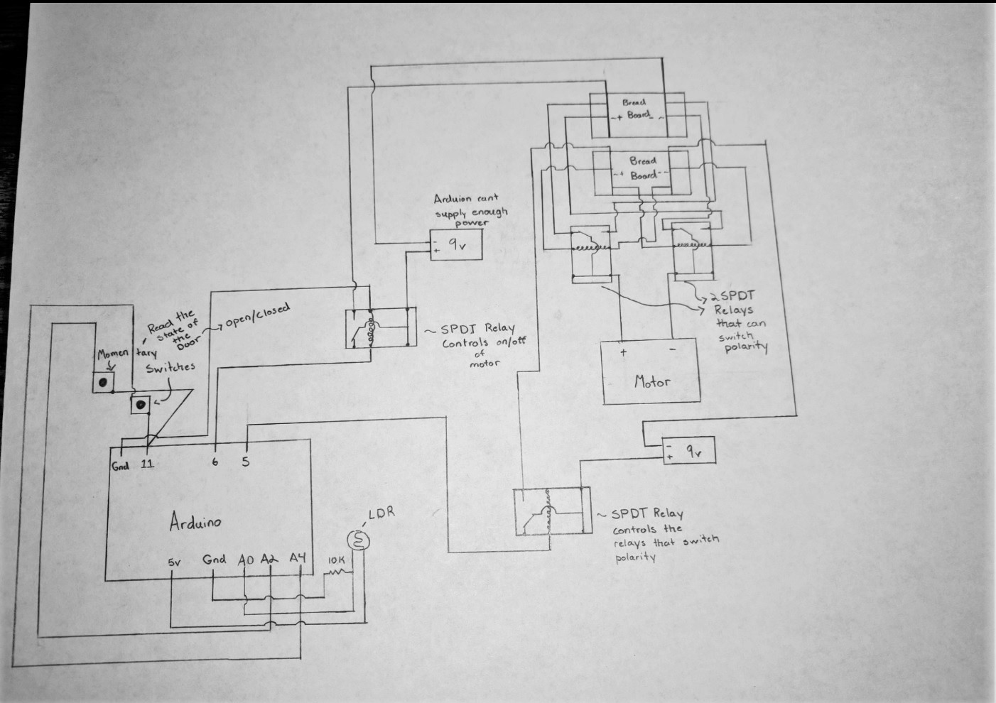
For a school project I need to create something that roughly relates to my career choice. I decided to create an automatic chicken coop door that would use a photo resistor to trigger the opening/closing of the chicken coop door. My circuit has a series of relays controlling the polarity and power to the motor that will open/close the coops door. The issue I'm running into is with the switches that read whether or not the door is open/closed. I can't figure out how to tell the Arduino that the door is closed but it's OK to reopen door. What I mean is I only figure out how to tell the Arduino to turn off the motor when the switch closes. I can't figure out how to tell the Arduino it can reopen when it's light again while the switch is closed.

~I looked into swithCase and it looks like it might solve the problem, but I don't know how to properly execute the code.~

Thanks any help is appreciated!
(I fixed the way I put the code into the question and created a schematic)


V6 has the code with the switch problem

int photocellPin = 0;     
int upswitchReading;
int downswitchReading;
int photocellReading;
int powerDown = 11;  
int powerUp = 9;


void setup(void) {
  pinMode(powerDown, OUTPUT);
  pinMode(5, OUTPUT);
  pinMode(6, OUTPUT);
  pinMode(powerDown,OUTPUT);

  Serial.begin(9600);   
}
 
void loop(void) {
  digitalWrite(powerDown, HIGH);
  digitalWrite(powerUp, HIGH);

 
  Serial.print("Up Stop reading = ");
  upswitchReading = analogRead(2);
  Serial.print(upswitchReading);     

  Serial.print("Down Stop reading = ");
  downswitchReading = analogRead(4);
  Serial.print(downswitchReading);  
  
  Serial.print("  Photocell reading = ");
  photocellReading = analogRead(photocellPin);  
  Serial.print(photocellReading);     
 

  if (photocellReading < 10) {
    Serial.println(" - Dark");
  } else if (photocellReading < 200) {
    Serial.println(" - Dim");
  } else if (photocellReading < 500) {
    Serial.println(" - Light");
  } else if (photocellReading < 800) {
    Serial.println(" - Bright");
  } else {
    Serial.println(" - Very bright");
}
if (photocellReading < 200) 
{ 
  digitalWrite (6,HIGH); //On Motor 
  digitalWrite (5,LOW);    // Polarity of Motor (if pin 5 is LOW motor polarity is Positive)
}
else 
{
  digitalWrite (6,HIGH); //On Motor 
  digitalWrite (5,HIGH); // Polarity of Motor (if pin 5 if HIGH motor polarity is Negative)
}
if (downswitchReading > 1015)
    digitalWrite (6,LOW); //Off Detection for Motor (Door Going Down)
if (upswitchReading > 1015)
    digitalWrite (6,LOW); //Off Detection for Motor (Door Going Up)
  delay(1000);
}

V7 has what I think a switchCase would look like. ( I get this error though = expected unqualified-id before 'switch')

int photocellPin = 0;     
int upswitchReading;
int downswitchReading;
int photocellReading;
int powerDown = 11;  
int powerUp = 9;

 
void setup(void) {
  pinMode(powerDown, OUTPUT);
  pinMode(5, OUTPUT);
  pinMode(6, OUTPUT);
  pinMode(powerDown,OUTPUT);

  Serial.begin(9600);   
}
 
void loop(void) {
  digitalWrite(powerDown, HIGH);
  digitalWrite(powerUp, HIGH);
  
  int photocellReading = analogRead(photocellPin / 3);
  int readingReal = map(photocellReading,54,974,0,100);
  
  
  Serial.println("Up Stop reading = ");
  upswitchReading = analogRead(2);
  Serial.println(upswitchReading);     

  Serial.println("Down Stop reading = ");
  downswitchReading = analogRead(4);
  Serial.println(downswitchReading);  
  
  Serial.println("  Photocell reading = ");
  Serial.println(readingReal);     

}
switch (readingReal)
{
  case 0:
  digitalWrite (6,LOW);        //On Motor 
  digitalWrite (5,LOW);         // Polarity of Motor (if pin 5 is LOW motor polarity is Positive)
break;
  case 1:
  digitalWrite (6,HIGH);      //On Motor 
  digitalWrite (5,LOW);         // Polarity of Motor (if pin 5 is LOW motor polarity is Positive)
  if (upswitchReading > 1015)
    digitalWrite (6,LOW);     //Off Detection for Motor (Door Going Up)
break;
  case 2:
  digitalWrite (6,LOW);       //On Motor 
  digitalWrite (5,LOW);         // Polarity of Motor (if pin 5 is LOW motor polarity is Positive)
break;

  case 3: 
  digitalWrite (6,HIGH);      //On Motor 
  digitalWrite (5,LOW);         // Polarity of Motor (if pin 5 is LOW motor polarity is Positive)
  if (upswitchReading > 1015)
    digitalWrite (6,LOW);     //Off Detection for Motor (Door Going Up)
break;
  default:
  digitalWrite (6,LOW);       //On Motor 
  digitalWrite (5,LOW);         // Polarity of Motor (if pin 5 is LOW motor polarity is Positive)
delay(1000);
}

The jpg is a photo of my schematic

What jpg would that be?

Sorry it didn't upload!It should be there now.

Why are the switches attached to pin 11? Do you have a flyback diode on the relay attached to the Arduino pin 6?

The switches get power from pin 11. They switches state gets read through analog pins 2 and 4.

I don't have a flyback diode attached to the relay. Should I have one, if so Why?

All DC relays should have a flyback diode across the coil to absorb high drop out voltages.
Google will help.

Suggest you drive the relays with transistors as an Arduino o/p handles only ~20mA.

.

PP3 9volt battery have little capacity.

Ok so how would I find the proper transistor?

PP3 9volt battery have little capacity.

Please explain why D11 is connected to A2 and A4.

One relay coil has no GND connection.

A 2N2222 might work.

What is the relay coil voltage and resistance?

.

This has been offered to other chicken coop lovers:

I put the battery in there to symbolize a power source other than the Arduino. I'm probably going to use either a high capacity rechargeable battery hooked up to a solar panel on top of the chicken coop or use an outlet

That relay is now grounded using the 2nd ground pin next to the 5v pin.

Here's a link to the relay I'd like to use-

https://www.jameco.com/Jameco/Products/ProdDS/174450.pdf

At 3V there's 25 Ohms of resistance (+/- 10%)

D11 is serving as a power supply

So I still can't figure out how to tell the Arduino it can reopen when it's light again while the switch (the momentary switches on the lower left that read the state of the door) is closed.

There are no pull down resistors on A2 or A4, therefore they will float and cause problems when the switches on D11 are open.

IMO a limit switch should break the actual current to a motor, not through software, but that’s up to you to deal with.

.

For the relay, use just about any small NPN transistor to activate the coil (2N3904, 2N2222). You will burn the Arduino pins if you try to drive the coil directly from an output.

Using D11 as a "power supply" for the buttons is not a good idea. Use the INPUT_PULLUP option on the input pin instead.

If I wire the switches so that they block the actual current then I have no way of restoring current to the motor without manual opening the door and closing the circuit again.

So I should add transistors to the relays
And run the switches from the input pin by using the command INPUT_PULLUP

When your voltage divider shows day time voltage, you reverse the current through the motor and stop it when the limit switch toggles.

BTW, you can use digital inputs instead on analog for the limit switches.

What is the rating of the motor?

You should add a bidirectional transorb across the motor, Vcc + ~20volts.

.

I'm planning on using a 5V stepper motor, but that is subject to change. It struggles some when closing the door so I'm probably going to bump up the power a bit. I tried to use a Digital Input, but I couldn't get a reading on the serial monitor, when I switched to analog it worked.

So what code would I use to restore power to the motor after the switch toggles?

Also what is bidirectional transport and why is it important in a circuit like this one?

I'm planning on using a 5V stepper motor, but that is subject to change. It struggles some when closing the door so I'm probably going to bump up the power a bit.
These have no torque, suggest you use a DC gear motor.

I tried to use a Digital Input, but I couldn't get a reading on the serial monitor, when I switched to analog it worked.
You need pulldown resistors ~10K.

So what code would I use to restore power to the motor after the switch toggles?
If you insist on a stepping motor, you reverse the stepping sequence.

Also what is bidirectional transport and why is it important in a circuit like this one?
An inductive load like a motor kicks up a lot of hash/noise when operating similar to voltage kick back form a relay. That should be a Transorb, similar to a back to back zener diode.
See:

If you don't place your limit switches as shown in the schematic I attached (post #10), suggest you have a 'crash' switch top/bottom to remove the motor from the circuit as a fallback.

Ok cool! So I'll will use a DC gear motor.

In my code how can I restore power to the motor after the switch toggles?

What specific area do I need to add something or take something away?

Was I on the right track with the switchCase?