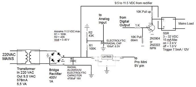
Measure Mains Voltage and control SSR

Hi all

We are constantly having "load shedding" in our country, where the sole power supplier cuts the mains power to different areas almost daily, for 2 hours at a time. ( Long story as to why and what public opinion is about this, but not relevant for this post )

It has been proven that the voltage of the mains supply, when restored by the supplier, is very erratic for quite some time after.

To avoid this 'dirty power' from damaging certain home office equipment, I am wanting to use a Pro Mini to do the following when the power is restored :

  1. check that the mains supply is above a certain voltage, and reasonable stable.
  2. control the restoration of the mains power to the equipment using an SSR ( pre-set time delay, say 15 minutes )

Phase two of the project will be the option to specify the time to wait, after mains power has stabilized, before restoring power to equipment ( in 5 minute increments )

Phase 3 will be to add a small ethernet module, and link to the existing DIY home automation and control system.

So the initial requirement is 2 part :

1 - measure the mains voltage
2 - control the SSR

I would be grateful if anyone could please look at the attached drawing, and comment if you think I may have missed something.

My calculations on the voltage divider are :
12 VDC = 3.837 V to analog input pin
8 VDC = 2.558 V

At the risk of telling you a bunch of stuff you already knew, here's some comments:

First, where I am, the voltage number they give for the mains voltage is an RMS value. If they do the same thing where you are, you're going to see greater than 12 Volts out of your transformer. Point is... If they do the same thing where you are, you haven't have sized your voltage divider resistors properly.

Second, I think your analog input voltage is going to be noisy due to ripple. I don't think 0.33 uF is enough capacitance to smooth the waveform coming off your bridge. You will probably get different voltage readings depending on where in the cycle you take your measurement.

Third, you are trying to measure the voltage level of an unregulated source, while at the same time you're drawing a changing amount of energy from that source. You have a variable load (SSR on vs. SSR off) on an unregulated supply and because of that, you are going to get more ripple when you turn on the SSR. If you're planning to draw 7.5 mA off your unregulated supply I can guarantee that your 0.33 uF cap isn't enough and the voltage you're trying to measure is going to be all over the place. Your microcontroller is going to be a variable load as well although compared to your SSR switching off or on, you might be able to ignore the microcontroller.

Fourth, Are you sure you're going to have enough resolution on your A/D output to resolve what it is you're trying to do? Account for the RMS voltage and size your divider accordingly and then calculate the theoretical number of bits change you'll have per volt change out at the 220 line? How much do you need and do you have enough?

Fifth, You really don't care about anything significantly below 220V, but you're going to burn resolution for it anyway. Maybe you need a more sophisticated analog front end. Concentrate on the area where you really care? Like between 200 and 240? Below or above that, you don't care about the actual value... All you care is that you are too high or too low. Maybe do more in the analog realm before you try to digitize it?

Hope that helps?

HACF:
First, where I am, the voltage number they give for the mains voltage is an RMS value. If they do the same thing where you are, you're going to see greater than 12 Volts out of your transformer. Point is... If they do the same thing where you are, you haven't have sized your voltage divider resistors properly.

OK. So the correct route would be to first measure the voltage from the AC-AC transformer and bridge rectifier ( before the LM7805 ), and then size the voltage divider resistors to suit that reading. My ( uneducated ) guess is that it may be better to size the resistors so that the analog voltage maximum is a lot lower than the 5V limit of the input pin - say somewhere around 2.5V ?

HACF:
Second, I think your analog input voltage is going to be noisy due to ripple. I don't think 0.33 uF is enough capacitance to smooth the waveform coming off your bridge. You will probably get different voltage readings depending on where in the cycle you take your measurement.

Understood. That 0.33 uF capacitor was taken from the spec sheet of the voltage regulator. I have since read some other articles that explain that the output of the bridge rectifier should be passed through a capacitor to "level out" and smooth the ripple in the DC current.

I have no idea how to determine what type of capacitor to use, nor what rating / specs it should have. Advice in this really appreciated.

HACF:
Third, you are trying to measure the voltage level of an unregulated source, while at the same time you're drawing a changing amount of energy from that source. You have a variable load (SSR on vs. SSR off) on an unregulated supply and because of that, you are going to get more ripple when you turn on the SSR. If you're planning to draw 7.5 mA off your unregulated supply I can guarantee that your 0.33 uF cap isn't enough and the voltage you're trying to measure is going to be all over the place. Your microcontroller is going to be a variable load as well although compared to your SSR switching off or on, you might be able to ignore the microcontroller.

OK. But if the SSR can be activated with an input range of 3-32VDC, could I not then rather use the 5V output of the LM7805 to activate the SSR ( instead of the 12V from the rectifier ). Would this still affect the voltage between the rectifier and the LM7805 ?

HACF:
Fourth, Are you sure you're going to have enough resolution on your A/D output to resolve what it is you're trying to do? Account for the RMS voltage and size your divider accordingly and then calculate the theoretical number of bits change you'll have per volt change out at the 220 line? How much do you need and do you have enough?

What I am aiming for here is to determine if the mains voltage is in the ranges :

  1. below 170VAC
  2. 170 to 200VAC
  3. 200 to 230VAC
  4. above 230VAC

Depending on the type of equipment being controlled by the SSR, I would use the mains voltage to determine if the mains is at a level that is sufficient to meet the requirements of the equipment. Some equipment has a power supply that can accept, lets say, 110 to 220VAC, while others may require an input of 220VAC.

HACF:
Hope that helps?

Yes, you have been a fantastic help. Thank You. Really appreciate the points you made.

DaveO:
Understood. That 0.33 uF capacitor was taken from the spec sheet of the voltage regulator. I have since read some other articles that explain that the output of the bridge rectifier should be passed through a capacitor to "level out" and smooth the ripple in the DC current.

I have no idea how to determine what type of capacitor to use, nor what rating / specs it should have. Advice in this really appreciated.

A bridge rectifier like that with a reservoir capacitor added will give you an output of about 15.5 V not 12 V.To calculate the value of the capacitor you need to work out the current that will be drawn and estimate the maximum ripple voltage you can stand. Then use the equation:

I = C x dV/dt which re-aranges to C = I x dt/dV

where I is the current you are drawing in Amps,
dt is the time between successive peaks, 0.01 seconds for 50 Hz supply
and dV is the peak to peak amplitude of the ripple in Volts.

Russell.

Here's some discussion and pictures about the full wave rectifier and the need for, size, and composition of the capacitor:
http://www.electronics-tutorials.ws/diode/diode_6.html

Yes, a simple way to size your voltage divider resistors would be to build that part of the circuit and just take some measurements. Those measurements should tell you how the incoming power is specified, but it would also make knowing that info immaterial. The bottom line is that you want the voltage into your A/D to be within range and sizing those resistors empirically would make sure that happens.

Just remember that a simple hand held voltmeter might not be telling you the whole story. If you've got ripple, your DC reading might not be accurate, and the A/C scale probably reads RMS. If you have any doubt, an oscilloscope would tell the truth.

could I not then rather use the 5V output of the LM7805 to activate the SSR ( instead of the 12V from the rectifier ). Would this still affect the voltage between the rectifier and the LM7805 ?

As for where you pick up the power for the SSR, as long as it's on the same side of the transformer as where you're measuring, it's going to cause the same problem. Your regulated 5V supply still draws energy from the same unregulated supply and changing loads on your 5V supply will cause the same ripple on the unregulated portion.

And yes, making sure your max analog input is lower than your reference is necessary and that's why I was poking around with the resolution questions. You'll need to make sure that at your max line voltage, you're still within the A/D input range and by the time and scale your input voltage accordingly.

Basically for the resolution, you're probably going to be down somewhere around two bits change per volt change on your input and all your numbers are going to be at the very upper end of your range. In other words, out of the entire 1024 different output states from your A/D, you're only ever going to care about 120 of them.

Honestly... If all your trying to do is determine four different voltage levels, this sounds like a job better suited to some comparators instead of trying to use the A/D. Adjust your thresholds with some resistors and read the comparators in on digital inputs instead of the A/D. Faster and you don't have to worry about the resolution issue.

You might also consider using a different transformer (or a second set of windings off the same transformer) for your sense voltage(s). Try to decouple the variable loads from your sensing function.

Measuring AC voltages as rms is standard, but a multimeter will report the rms value if you want to check.

If the input voltage is 230 VAC rms for 12 VAC rms output on the transformer, then the peak voltage from the transformer will be almost 17 V (a factor of sqrt(2) higher). The bridge rectifier will subtract two diode drops, so your "12V DC" power supply will actually produce about 15.5 V. Your resistive voltage divider will output about 4.9 V for 230VAC rms input.

15V is too much for the Arduino, so you either need an additional regulator or use a 9VAC transformer. The additional regulator would be a better choice, and I suggest to use 9V.

Thanks all for the replies.

After thinking about my requirements, I only need to measure the mains voltage BEFORE activating the SSR.

Once the SSR is 'on', the project is no longer concerned with the mains voltage.

So when the mains voltage fails, the power to the Arduino also fails.

When power is restored, the Arduino will boot, wait 10 seconds, check the mains voltage ( then activate the SSR if the pre-set criteria is met )

Loop will check every 10 seconds until the mains supply meets the criteria. Once the criteria is met, then the SSR simply remains on until the next power outage.

So based on this, I can ignore the effect that the SSR has on the circuit when it is on.

As far as I can tell, the only item that I am missing on the drawing would be a smoothing capacitor between the output terminals of the bridge rectifier.

And if C = I x dt/dV
where I is the current you are drawing in Amps,
dt is the time between successive peaks, 0.01 seconds for 50 Hz supply
and dV is the peak to peak amplitude of the ripple in Volts.

C = 1 x 0.01 / 15.5 ( assuming max current for LM7805 - 1A and using 15.5V as example until actual real value is measured )

C = 6.45 ( is this result in 'F', so 6.45F = 6,450,000 uF ? )

C = 0.01/15.5 = 645 uF

If you use for example a 9V regulator, then the allowable ripple can be around 3V. But 1 ampere is unrealistic. Assuming 100 mA:

C =0.1*0.01/3 = 333 uF. Bigger is OK, so 1000 uF should do and is a typical value used in such circuits.

jremington:
C = 0.01/15.5 = 645 uF

If you use for example a 9V regulator, then the allowable ripple can be around 3V. But 1 ampere is unrealistic. Assuming 100 mA:

C =0.1*0.01/3 = 333 uF. Bigger is OK, so 1000 uF should do and is a typical value used in such circuits.

OK. So I should change the AC/AC transformer to one with a 9VAC output and am then looking for an Electrolytic type capacitor, 1000 uF, at least 9V. Correct ?
Is there a maximum voltage rating for the capacitor that should not be exceeded ? I have seem some 24V caps lying around.

DaveO:
After thinking about my requirements, I only need to measure the mains voltage BEFORE activating the SSR.

So based on this, I can ignore the effect that the SSR has on the circuit when it is on.

Yeah, I was wondering about that. I wasn't sure if you needed or wanted to continue to measure the voltage after you had decided that everything is OK and had turned the SSR on. If you can ignore the SSR current then you might be able to assume the microcontroller current is a constant draw and factor that into your design.

I'm pretty sure you get it now, but just to make sure... Current draw from your unregulated supply is OK as long as that current draw is constant (enough) and doesn't change.

And you're not using the formula C = I x dt/dV quite correctly.

The "I" is your actual current draw, but it appears that you have used the maximum that the 7805 will handle. You're not going to draw the max the regulator can deal with... The number you want is what your microcontroller will draw plus some additional fudge factor to account for things like quiescent current the regulator requires to operate. Probably in the milliamp range, not anywhere near 1A.

Also, the "dV" is the peak to peak amplitude of the desired ripple, and you have used your entire voltage swing for that number instead. As an example, you might decide that 100 millivolts ripple is the max you can tolerate, and in that case, you would use 0.100 Volts.

So, for example, if you are going to draw 50 mA out of your 50 Hz unregulated supply and you have decided that you can't tolerate more than .1V ripple, you would calculate that you need about a

C = .05 * (.01/.1) = .005 F or 5000 uF.

Lower current draw or higher allowable ripple would result in a smaller cap. I just pulled numbers out of the air.

So I should change the AC/AC transformer to one with a 9VAC output and am then looking for an Electrolytic type capacitor, 1000 uF, at least 9V. Correct ?
Is there a maximum voltage rating for the capacitor that should not be exceeded ? I have seem some 24V caps lying around.

Those are all commonly used values. The maximum voltage rating on the capacitor must be higher than any voltage you expect it to encounter, but it can be anything greater than that.

A 9VAC transformer and the bridge circuit will produce about 11.5 VDC.

My sincere thanks again for all the replies and guidance.

I have been looking at the capacitors, like this one :

but what concerns me is the spec for the 'lifetime' - in this items case = 2000h. Now that's less than 3 months ! Surely that can't be right. What am I not understanding that would make that spec OK to use ?

OK. I can't believe that the life of a capacitor would be measured in such a short period of time, so am going to assume that the spec is talking about the life span if the cap is used at its max temperature, or some other odd situation.

I have modified the drawing and changed the transformer to 9,5VDC, and added a 4700uF 16V cap after the rectifier.

I think the last question I have not considered, is : should the output voltage of the AC to AC transformer always be relative to the input mains voltage ?

So if 220V in = 9.5 V out,
would it be correct to assume :
200 V in = 8.636 V out
180 V in = 7.77 V out

Calculated as : 9,5V / 220V = 0.0431V out for every 1V in.

If a transformer is not heavily loaded, the ratio of the voltage input to output is a constant.

With a 9.5 VAC transformer and no voltage regulator, you are again exceeding 12 V on the Arduino RAW power input pin.

DaveO:
OK. I can't believe that the life of a capacitor would be measured in such a short period of time, so am going to assume that the spec is talking about the life span if the cap is used at its max temperature, or some other odd situation.

I have modified the drawing and changed the transformer to 9,5VDC, and added a 4700uF 16V cap after the rectifier.

I think the last question I have not considered, is : should the output voltage of the AC to AC transformer always be relative to the input mains voltage ?

So if 220V in = 9.5 V out,
would it be correct to assume :
200 V in = 8.636 V out
180 V in = 7.77 V out

Calculated as : 9,5V / 220V = 0.0431V out for every 1V in.

Yes, that quoted capacitor life is for use at the maximum rated ripple current which gives rise to internal heating. I doubt that you will have any problem.

Your revised schematic looks OK.

The ratio of the mains voltage to your measured voltage will not be constant as the voltage drop on the rectifier does not vary in the same way. However it should be near enough for your purposes.

Russell

jremington:
If a transformer is not heavily loaded, the ratio of the voltage input to output is a constant.

With a 9.5 VAC transformer and no voltage regulator, you are again exceeding 12 V on the Arduino RAW power input pin.

Hi jremington

Thank You again for your input.

The Arduino should be protected with the 7805 Voltage Regulator supplying the 5VDC that the Arduino requires, and the voltage divider limits the input to the analog pin to a max of 3.5V

Or am I missing the point of your comment ?

Sorry, I misread the diagram. It looks OK.

Hi Russell

Thank You also for your input and comments. I am learning so much today.

russellz:
Your revised schematic looks OK.

Thank You. It takes some time to get components in this corner of Africa, so I like to make sure of things as much as possible before ordering.

russellz:
The ratio of the mains voltage to your measured voltage will not be constant as the voltage drop on the rectifier does not vary in the same way. However it should be near enough for your purposes.

OK. I had not thought of that. So even if the transformer output was exactly constant / relative to the mains input, the voltage drop over the rectifier diodes is NOT constant and changes on a curve, depending on the diode input voltage. That makes sense.

Maybe once I have the board assembled and working, I should find a local guru with an oscilloscope and a variable voltage power supply, to create the mains supply conditions that I am interested in ( 170VAC, 200VAC, 230VAC ) and then use the Arduino to report the exact analog pin value for each that it is reading from the voltage divider.

Just started to read this posts.
I would make the resistor values of the voltage divider at least 10x bigger, and use a smoothing cap (10-100uF) from analogue-in to ground.
Measuring/sampling the mains voltage becomes easier without the ripple from the primary cap. And any spikes are also suppressed.
That said, my prefered choise would be to supply the Arduino from a standard switchmode plugpack.
And read the mains voltage from a separate very small/cheap transformer (with bad regulation).
Also no 7805/Arduino load variation problems that way.
Rolling your own supply might be a good exercise, but by the time you have all the parts and have put it in an enclossure, you will have spend a lot more.
If the SSR only needs >=2.4volt and <15mA, why the transistor. Why not drive it directly from an Arduino output.
Leo..

Hi Leo

Thank You for your input.

So your suggestion is to increase the resistors for the voltage divider to lower the current ? Sounds like a good idea.

My calc tells me that using 100K and 43K would give results in the required range ( input 11.5V, out 3.45V ).

I have also updated the drawing ( attached ) with a 100uF 6.3V cap between the analog input pin and ground.

For the scope of this project, I don't see any benefit of using a separate power supply for the Arduino.

It takes up additional space, adds cost, and the draw from the Arduino and the LM7805 should always be reasonably constant ( after startup and before activating the SSR ) so if we attach an oscilloscope to get the exact analog values for the required voltages, then I don't see any reason why these would / could change to any large degree.

Anyone have any thoughts or comments / additions to this approach ?