Hi ppl,
I've started a project to control the weld time to weld 18650 cells. All works well till i connect the load, an MOT. When connected not sure why the TRIAC does not switch on when the gate is triggered via the opto coupler.
Hi ppl,
I've started a project to control the weld time to weld 18650 cells. All works well till i connect the load, an MOT. When connected not sure why the TRIAC does not switch on when the gate is triggered via the opto coupler.
Not sure why it does that, but there are other strange things in the diagram.
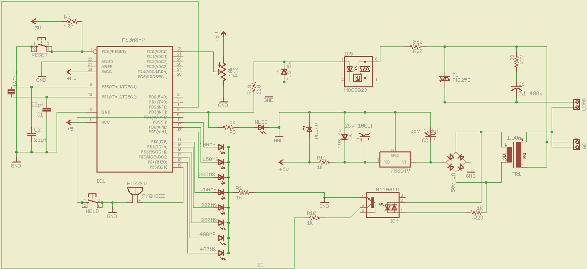
Why 5volt TVS diodes across the opto LED and on the 7805 output. Tits on a bull?
I would rather use a suitable TVS diode on the regulator's input than on the output.
The input cap of the 7805 is too small, and mains ripple will almost certainly be on the 5volt line.
I would use 1000uF minimum.
Regulator output cap value is ok, but I would add a 100n ceramic cap.
And certainly add 100n caps on the chip's VCC.
Why a 1k resistor in series with the zero crossing transistor. Does the pin have pull-up?
R11 must be a drawing mistake. +5 connects on the other side of R11
OP's picture attached.
Leo..
Why 5volt TVS diodes across the opto LED and on the 7805 output. Tits on a bull?
thought the TVS 1N5908 could be replaced with a zener diode as i did not get them locally. so temporarily used these.
Why a 1k resistor in series with the zero crossing transistor.
hat is a current limiting resistor
Why a 1k resistor in series with the zero crossing transistor.
That would be another current limiting resistor for the power LED.
OP's picture attached.
??????????
I was talking about R10.
The transistor is (should be) connected to an input, hopefully with pull-up enabled in pinMode. Because you have no external pull-up resistor.
R10 is useless here.
I have attached your Eagle.sch as a picture, so posters without Eagle installed can also see it.
Leo..
Ah the R10, Well i thought connecting PIN 4 without a resistor would short things out. hence the resistor. yea the pin is actually PULLUP enabled and removed the resistor as well. I was under the impression that connecting those pins to ground without a resistor damage the atmega chip. I'll be replacing the TVS with 1N5908 and replacing the 1000uf 25v caps. 1000uf 10v be ok here (seems to be working ok). could not find the 100nf ceramic would the 22pf be ok ?
What else would you suggest ? what about the TRIAC its this one the BTA08-600B
anishkgt:
1000uf 10v be ok here (seems to be working ok).could not find the 100nf ceramic would the 22pf be ok ?
What else would you suggest ? what about the TRIAC its this one the BTA08-600B
Probably not. A 9volt transformer could, worst case, generate up to 14volt DC.
22pf or 100000pf is quite a difference. 100n ceramic caps are as common as 1k and 10k resistors.
Thyristor seems ok, but no real experience driving big inductive loads like microwave transformers.
Try with a 60watt lightbulb first?
Leo..
Note that your 5V power supply circuit causes loss of opto-isolation through your zero cross circuit (IC4). Also, you may have considerable distortion on TR1 secondary that becomes worse when the load is connected. Have you viewed the secondary waveform with a scope?
dlloyd:
Note that your 5V power supply circuit causes loss of opto-isolation through your zero cross circuit (IC4).Also, you may have considerable distortion on TR1 secondary that becomes worse when the load is connected. Have you viewed the secondary waveform with a scope?
Please explain further.
Would the zero crossing part be affected?
Maybe someone can explain why a zero crossing detector is used for spot welding.
Turning the load on at the top of the sine wave?
AFAIK switching an inductive load at zero crossing is not good.
Leo..
The GND is common to both sides of IC4 ... would need a separate 5V supply for full opto-isolation.
I think so. Also, a opto isolated zero cross circuit that's on the primary side would work much better and it would have complete isolation from the DC power rails.
dlloyd:
The GND is common to both sides of IC4 ... would need a separate 5V supply for full opto-isolation.
I think so. Also, a opto isolated zero cross circuit that's on the primary side would work much better and it would have complete isolation from the DC power rails.
The optocoupler is used for zero crossing, not for isolation.
The important part is that the opto LEDs are off during the time of zero crossing, and so is the opto transistor.
Not important with an optocoupler where the AC comes from. Primary or secondary.
But a higher AC voltage could make the zero crossing pulse narrower.
Leo..
But a higher AC voltage could make the zero crossing pulse narrower.
Yes, much narrower, closer to the true zero cross signal and less influenced by distortion (distortion on the primary would be much lower).
The transformer rating of only 1.5VA seems too low to both power the DC supply (bridge rectifier and 100µF capacitor), MCU and zero cross circuit. I think this low rating will allow considerable distortion to appear on the secondary signal.
Still in the dark about the need for a zero-crossing circuit for an inductive load.
Maybe someone can explain why a zero crossing detector is used for spot welding.
Turning the load on at the top of the sine wave?
From previous understanding of the OP's project and his code, he is indeed switching the load at the top of the sine wave.
Sorry, I removed the post with the first quote after reading this article about spot welding with a microwave transformer.
http://www.avdweb.nl/arduino/hardware-interfacing/spot-welder-controller.html
The author just connects a transformer terminal via a lowpass filter to an input. No opto.
Inductive load switching is also explained in the article.
Leo..
The author just connects a transformer terminal via a lowpass filter to an input.
There was a lengthy thread here Zero Cross Sensing with PulseIn() - General Electronics - Arduino Forum where using the zero cross detector H11AA1 instead of the direct connection of the AC signal to an interrupt pin was discussed.
cattledog:
There was a lengthy thread here Zero Cross Sensing with PulseIn() - General Electronics - Arduino Forum where using the zero cross detector H11AA1 instead of the direct connection of the AC signal to an interrupt pin was discussed.
We have come a long way from there and the zero cross is detected. The only problem now is that the MOC3023 (the same is used here) does not seem to be triggering the TRIAC? Albert in his website uses two Thyristors instead of a TRIAC, as he says TRIACs do switch off unless a zero crossing has reached. would that be a reason to look at ? Albert in his schematic uses the same optocoupler to drive the two thyristors. Will try a bulb as suggested by @wawa.
The schematic to drive the TRIAC was taken from the respective optocoupler's datasheet.
The transformer rating of only 1.5VA seems too low to both power the DC supply (bridge rectifier and 100µF capacitor), MCU and zero cross circuit. I think this low rating will allow considerable distortion to appear on the secondary signal.
I don't think so as it is the same circuit used in Albert's design. Moreover the ATmega works and does detect the zero cross and sends out a pulse too, yet to verify it with an oscilloscope which i have ordered.
Hi,
The schematic to drive the TRIAC was taken from the respective optocoupler's datasheet.
What makes you think your MOT is RESISTIVE, thats the config you have wired up for, trying your project with a Lamp instead of the MOT is a good idea.
An MOT is a HIGHLY INDUCTIVE load.
Tom... ![]()
Was actually following this as I've ordered the MOC3023. Did i buy the wrong optocoupler ? and am i following the wrong schematic here ?
This is what i thought was correct
Hi,
The transformer rating of only 1.5VA seems too low to both power the DC supply (bridge rectifier and 100µF capacitor)
OP response
I don't think so as it is the same circuit used in Albert's design.
Hmm... Do you have a DMM, can you measure the voltage at the input to the regulator please.
Moreover the ATmega works and does detect the zero cross and sends out a pulse too, yet to verify it with an oscilloscope which i have ordered.
How have you determined this?
Can you post YOUR circuit diagram please, not in Eagle format but jpg or png please. (Eagle can export a graphics file I believe.)
Thanks.. Tom.. ![]()
Hi again,
Did you check the parameters of the suggested TRIAC
http://www.profesormolina.com.ar/electronica/datasheets/downloads/tic253.pdf
and the one you are using?
Albert in his schematic uses the same optocoupler to drive the two thyristors.
What Albert schematic, and what two thyristors?
Tom...