this might come along as a redundant, but i have not found a single piece of info regarding how to run and control this.
i connect the linear actuator to the arduino: red to +5V, black to GND and yellow to pin9. the actuator turns on and extends to full length. then...nothing!!!
please help me out. am i missing something?
then i went and bought a adafruit motor shield and now i am not sure how to connect it to arduino.i did connect it (i guess) and ran the "sweep" code but nothing!!!
please help me...it might well be a small issue but it for sure is quite urgent. i appreciate any help.
If they are -R versions, then yes afaik they should run as servos.
But the problem is probably that the Arduino doesn't have the current. So hook it up with its own 5V supply to its red and black, hook the L12 ground to the Arduino ground, and give Arduino its power as normal...
Edit... and even without the shield it should be ok, with yellow to whichever pin you attached the Servo to in the sketch.
Hello and thank you so much for your comments.
The actuator says -P on the cylindrical box.
i had pin 9 of the PWM for this purpose.
But for your method, could you explain a bit more in detail please?
I do not think i understood the way you mentioned for the sufficient current.
thank you.
Well, according to Figelli L12-P page, the -P version is not a servo, it has no control built in. It says it has a potentiometer built in though, to provide position feedback. I think that means you have to read the poetentiometer on an analog pin, where presumably a reading of 0 (0v) would be one end of the travel and 1023 (5v) would be the other end.
I've never used one, but I suppose if you wanted it to go half way, you would apply power and in a loop, read the potentiometer on the analog pin on every pass, and switch off when it was at about 500.
So it's kindof like a servo, but a servo doesn't have feedback... here, you're kindof providing the servo position control "long-hand" but have the added advantage of knowing where the thing has extended to. With a servo you never know if it's where you think it is.
Regarding the current thing, well it's simply that the Arduino 5v can only provide a limited currrent, I forget the value, but it's barely enough to drive an unloaded hobby servo, hence the need for direct power, not thru the Arduino.
EDIT: I also guess that for the -P you'll have to drive it like a motor through a bridge to get both directions, not sure- so you may well need to attach it to shield.
oh!
i am glad i found what version it was, thank you very much.
now that it is different then how do i connect it to the arduino mega 2560? red to 5V, black to GND and what else? do i still use the yellow? if yes, where do i hook it up to? and what kind of code should i be using? am i going to write my own? if yes which library should i use? would you by any chance have a sample code so i can use?
many thanks.
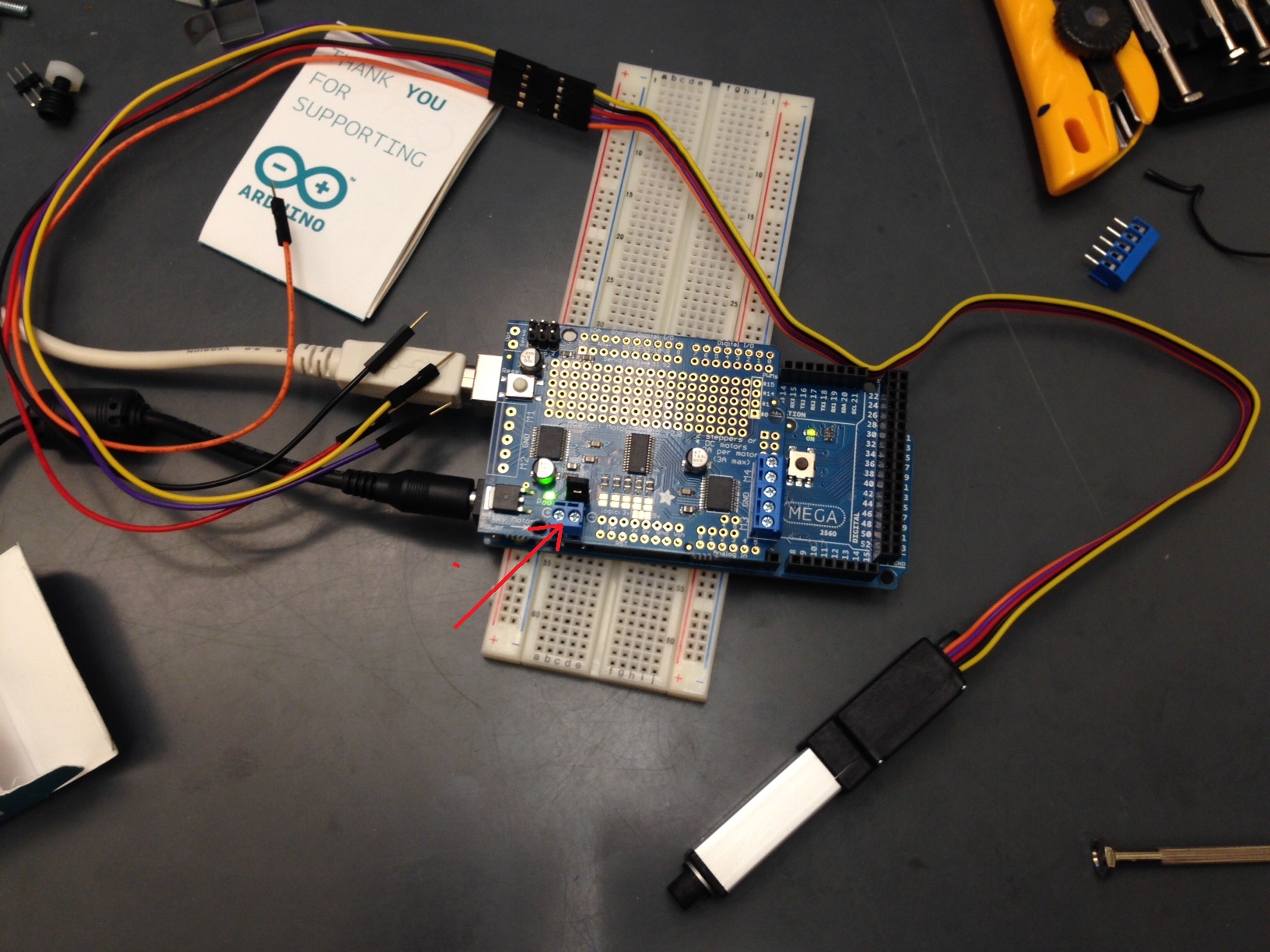
I'm not sure how to hook it up, it looks like it has more than three wires in the photo?
I think it will have to be connected just like any other motor, that is driven through the shield to give it speed and direction. (The reason it flew to the far end when you connected it up, was just that it's a simple motor and all you did was turn it on to full speed). So read up on how to drive a normal motor (not a servo) thru the adafruit shield. You will be able to send the actuator back and forward with a simple sketch just "guessing" how long to power it for so it gets to the point you want.
THEN and imo only then, read the tutorials on reading potentiometers. Then read the value from the -P's potentiometer wire (the yellow one? I don't know) and you will likely see it's "0" when the actuator is at one end and "1023" at the other. Then use those values in a loop to help position it.
But get the thing running under "dead reckoning" first just as a simpe on/off motor, maybe with PWM, but probably not necessary.
I emphasise I'm guessing here, never having seen one... Your Mileage May Vary
EDIT.... seems the -R version is muuuuuuuch easier, but not as precise.
The potentiometer has three connections as one would expect... The purple one is the wiper, the orange and yellow are the ends of the pot. Once you do the potentiometer tutorial, that will make sense.
If you want to control direction and speed of movement, you could use an h-bridge like below. Note that the below h-bridge may have up to 2v drop across it.
Thank you for your kind responses. I did not however quite understand: so I am not going to be able to run the actuator solely on the basis of JUST the Arduino Mega 2560?
Secondly, if not, how do I connect the ADAfruit to the Arduino Mega 2560? and I did not catch the part for the connections...as you definitely know there are 5 pins to the actuator: yellow, black, red, purple and orange...
Would you please advise?
Also, is there a sample code for the Firgelli L12 -P linear actuator, to run and control basic motion?
First it has a normal DC motor: to run that motor, especially if you want to reverse direction and perhaps control its speed, you need something like the adafruit shield. You'll need to read up on that shield and I'm sure adafruit's site has sample code. That will let you run the motor in both directions, but you won't knw where it has extended to, so....
Second, the value of the potentiometer tells you where it is. You need to read the potentiometer: check the tutorial here on Arduino site to see how to read analog values. Check the -P datasheet for the connection colours: the red and black drive the motor, the other three are the potentiometer: the purple one is the one you read on an analog pin of the Arduino. You move the motor until the reading on the pot tells you it's in the right place.
I don't know if there's any code to get you going.
behzadjk:
How could I make it move back and forth?
You should try what I suggested already and look at adafruit for guidance and code on using the shield to reverse a motor. Your actuator is just a motor after all: if you put the red and black onto a battery one way it will move one way, reverse the connection and it will shoot off the other way. That's what a shield like adafruit's does: it allows you to reverse direction under Arduino control, by changing polarity of the motor connection inside the shield's chip.
Here, I've saved you a step: Here is the adafruit shield page at adafruit. Click the Tutorials tab, and off you go. It even has libraries to download to get you going.
Hi, I think you need to do a lot of reading to understand what you need to do, to connect your actuator motor to the adafruit you need to read the online information that they provide for you.
Goto adafruit and look at the pages of information that they have on how to drive your DC motor back and forth.
We can/will not write all your code, to learn, try and do individual parts of this project one step at a time.
We can help with suggestions of code and where to start.
In this case the first thing is to get your motor running under control of the arduino forward and reverse.
Next would be reading the position pot.
Next calculating difference between where the actuator is and where you want it to be.
Next what direction to drive the motor.
One step at a time, may be slow but will mean you learn and we can help you best.
Tom...
the first thing is to get your motor running under control of the arduino forward and reverse.
Next would be reading the position pot.
Next calculating difference between where the actuator is and where you want it to be.
Next what direction to drive the motor.
One step at a time, may be slow but will mean you learn and we can help you best.
Which is kinda what I was trying to say, but falling on deaf ears?
I appreciate your responses here...i do not have a problem for the rest of the code to the pot working and the PID running.
my problem is that i cannot even get the example code from Adafruit, working!!! i have read every single line of the Adafruit regarding the DC motor, as my L12 is actually a DC motor with pot feedback signal. could you please help me out with the forward and backward motion ? is there a specific sequence i am not following?
We can't see what you are doing since you're not posting code.
But the general approach is to output a high and a low on whatever pins go from the Arduino to the motor boards direction control pins, then to reverse you swop the high / low to be low / high. You would put a delay between the two to let it run for a short while.
Something like this:
int ControlPin1 = 9; // or whatever
int ControlPin2= 10; // or whatever

void setup()
 {
pinMode(ControlPin1, OUTPUT);
pinMode(ControlPin2, OUTPUT);
}

void loop()
{
//forward
digitalWrite(ControlPin1, HIGH);
digitalWrite(ControlPin2, LOW);
delay(500); // or however long it takes to extend

//backward
digitalWrite(ControlPin2, HIGH);
digitalWrite(ControlPin1, LOW);
delay(500); // or however long it takes to retract
}