Control led with relay

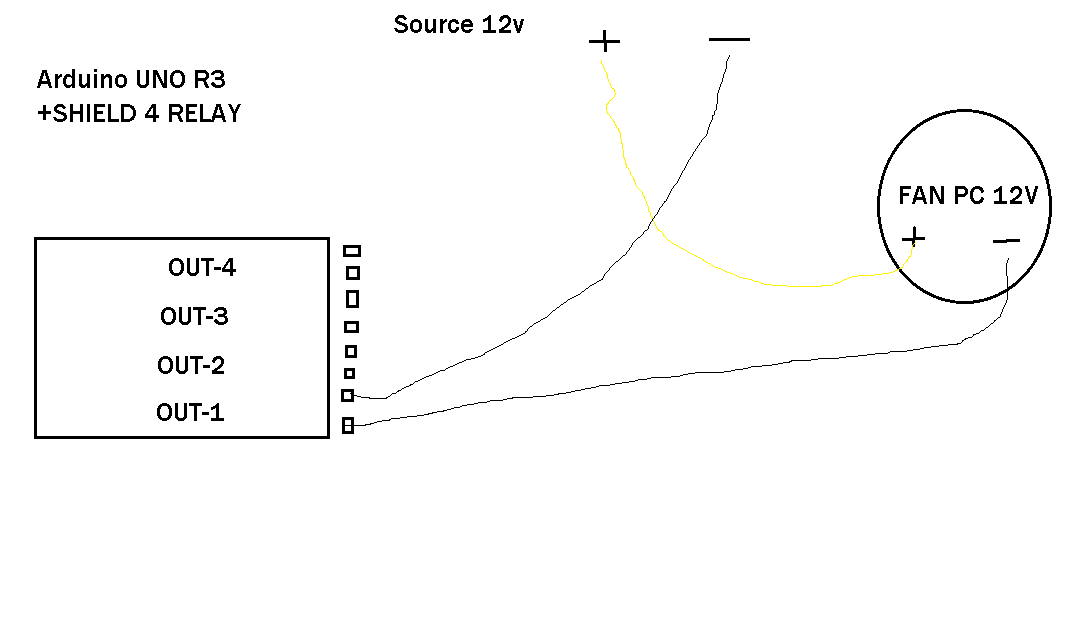
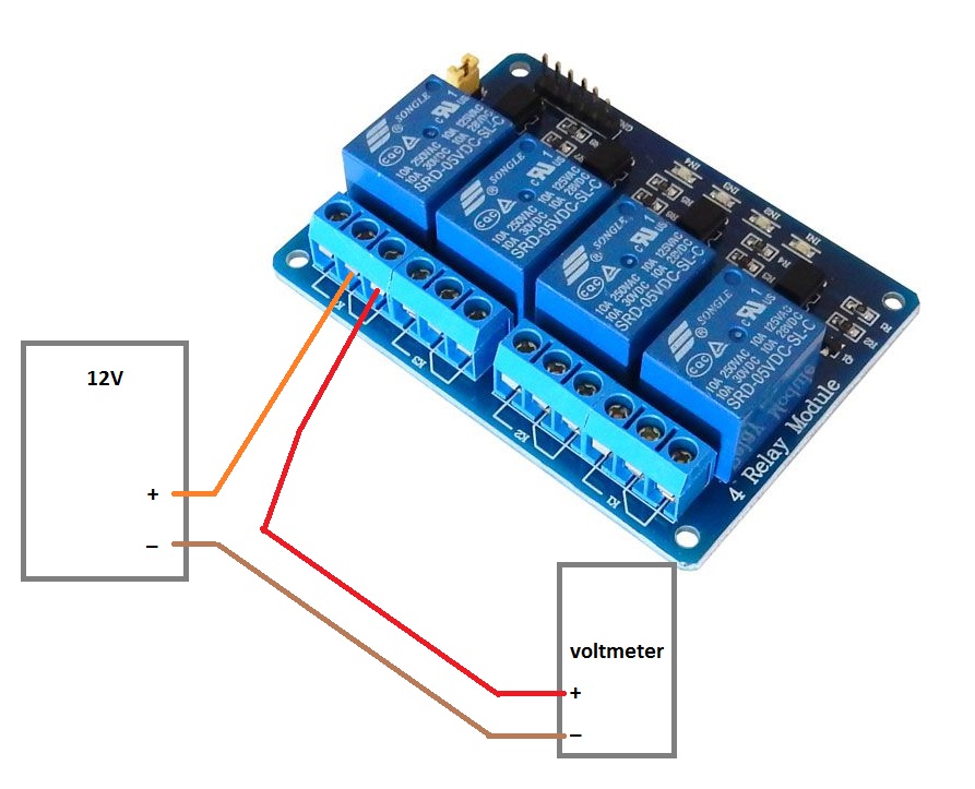
Hello I have an arduino uno, a shield 4 relays for controlling a motor in 2 directions by voice command, so I first wanted to try to run the relay without voice control with LED or a 12v fan pc, nothing works, I have the 12 volt external power required, one for the fan but nothing, I'm the click of the 4 relays with this code:

// Define constants and variables
const int out1 = 5; // define Arduino pin connected to relay 1
const int out2 = 6; // define Arduino pin connected to relay 2
const int out3 = 7; // define Arduino pin connected to relay 3
const int out4 = 8; // define Arduino pin connected to relay 4


// Initialization
void setup() 
{                
pinMode(out1, OUTPUT); // initialize the digital pin as an output     
pinMode(out2, OUTPUT); // initialize the digital pin as an output
pinMode(out3, OUTPUT); // initialize the digital pin as an output
pinMode(out4, OUTPUT); // initialize the digital pin as an output
Serial.begin(9600);    // Serial Port initialization
}

// enable or disable a relay (1 to 4)
void setRelay(int relay, int value)
{
if(relay > 0 && relay < 5) digitalWrite((relay + 4), value);
}

// main loop
void loop() 
{
setRelay(1, 1);                        // enable relay 1
Serial.print("Relay 1: Enabled ... ");
delay(1000);                           // wait for a second
setRelay(1, 0);
Serial.println("Disabled");            // disable relay 1
delay(1000);                           // wait for a second
setRelay(2, 1);                        // enable relay 2
Serial.print("Relay 2: Enabled ... ");
delay(1000);                           // wait for a second
setRelay(2, 0);                        // disable relay 2
Serial.println("Disabled");
delay(1000);                           // wait for a second
setRelay(3, 1);                        // enable relay 3
Serial.print("Relay 3: Enabled ... ");
delay(1000);                           // wait for a second
setRelay(3, 0);                        // disable relay 3
Serial.println("Disabled");
delay(1000);                           // wait for a second
setRelay(4, 1);                        // enable relay 4
Serial.print("Relay 4: Enabled ... ");
delay(1000);                           // wait for a second
setRelay(4, 0);                        // disable relay 4
Serial.println("Disabled");
delay(1000);                           // wait for a second
}

I also tried this:

void setup()

{

pinMode(5, OUTPUT);
}


void loop()
{
digitalWrite(5, HIGH); delay(1000);
digitalWrite(5, LOW); delay(1000);

But nothing, what should I do? Thank you for answering me .
Best regards .

what should I do?

Read the how to use this forum sticky post. Then edit that first post to put the code in code tags.

Then post a schematic, not a Fritzing layout abortion, of your circuit. Pen and paper to draw it is fine.

Thank you for the answer, I tried to do what I could for the schematic ,for information to the shield 4 relay is mounted directly on Arduino and has a power supply unit 12 dc. Best regards

I tried to do what I could for the schematic

So where is it?

information to the shield 4 relay is mounted directly on Arduino and has a power supply unit 12 dc.

Sorry but that doesn't describe anything precise enough to be useful.

Grumpy_Mike:
So where is it?

the schematic is attached with the message

The shield is MR007-002.

Best regards

What is missing is the labelling on the relay output. The wires you should be using will be called common and N/O for normally open.

If the fan still will not go on when the relay clicks then it is not wired as your diagram.

Grumpy_Mike:
What is missing is the labelling on the relay output. The wires you should be using will be called common and N/O for normally open.

If the fan still will not go on when the relay clicks then it is not wired as your diagram.

How do I do please?

Best Regards.

Are you asking me how to connect wires to a thing that you have already connected wires to?

I am telling you what connections to attach the wires to. I am not sure there is any more information to give.

Good evening, the shield 4 relay has 2 pins on each trip, I just program the relay 3 to 4 seconds of contact, and 2 seconds of opening, I mean well over except that the 2-pin OUT-3 I n 'have anything that comes out the multimeter, what to do?
Best regards.

The attached drawing shows an example using Relay_4 of a 4-relay board.

Link to the MR007-002 shield.

Note there's a "Run/Prog" switch ... did you put it back in "Run" mode after programming?

Looks like there's only 2 terminals per relay ... probably NO and COM.
Just connect 12V to one terminal and the fan +12V wire to the other.

The relay board needs power, the Arduino needs power and the fan needs switched power ... show us a diagram/sketch of your connections.

Looks like there's only 2 terminals per relay ... probably NO and COM.
Just connect .......

Just like you showed on your origional diagram you posted. Make sure the connection are for the relay you are switching. Test this with the continuity setting of your meter.

Yeah, Just like you showed on your original diagram you posted.

HELLO in fact, it was the tension that was not 12v , now here is the code that works but I would put a timer to turn off the relay , thank you to answer me . Best regards

#include "Arduino.h"
#if !defined(SERIAL_PORT_MONITOR)
#error "Arduino version not supported. Please update your IDE to the latest version."
#endif

#if defined(SERIAL_PORT_USBVIRTUAL)
// Shield Jumper on HW (for Leonardo and Due)
#define port SERIAL_PORT_HARDWARE
#define pcSerial SERIAL_PORT_USBVIRTUAL
#else
// Shield Jumper on SW (using pins 12/13 or 8/9 as RX/TX)
#include "SoftwareSerial.h"
SoftwareSerial port(12, 13);
#define pcSerial SERIAL_PORT_MONITOR
#endif

#include "EasyVR.h"

EasyVR easyvr(port);

const int out3 = 7; // define Arduino pin connected to relay 3
//Groups and Commands
enum Groups
{
GROUP_1 = 1,
};

enum Group1
{
G1_OUVRIR = 0,
G1_FERMER = 1,
};

int8_t group, idx;

void setup()
{
// setup PC serial port
pcSerial.begin(9600);

// bridge mode?
int mode = easyvr.bridgeRequested(pcSerial);
switch (mode)
{
case EasyVR::BRIDGE_NONE:
// setup EasyVR serial port
port.begin(9600);
// run normally
pcSerial.println(F("---"));
pcSerial.println(F("Bridge not started!"));
break;

case EasyVR::BRIDGE_NORMAL:
// setup EasyVR serial port (low speed)
port.begin(9600);
// soft-connect the two serial ports (PC and EasyVR)
easyvr.bridgeLoop(pcSerial);
// resume normally if aborted
pcSerial.println(F("---"));
pcSerial.println(F("Bridge connection aborted!"));
break;

case EasyVR::BRIDGE_BOOT:
// setup EasyVR serial port (high speed)
port.begin(115200);
// soft-connect the two serial ports (PC and EasyVR)
easyvr.bridgeLoop(pcSerial);
// resume normally if aborted
pcSerial.println(F("---"));
pcSerial.println(F("Bridge connection aborted!"));
break;
}

while (!easyvr.detect())
{
Serial.println("EasyVR not detected!");
delay(1000);
}

easyvr.setPinOutput(EasyVR::IO1, LOW);
Serial.println("EasyVR detected!");
easyvr.setTimeout(5);
easyvr.setLanguage(5);

group = GROUP_1; //lancement du groupe (customisé)

pinMode(7, OUTPUT); // NE PAS METTRE PIN 12 OU 13 DEJA UTILISES PAR LE SERIAL
}

void action();

void loop()
{
if (easyvr.getID() < EasyVR::EASYVR3)
easyvr.setPinOutput(EasyVR::IO1, HIGH); // LED on (listening)

Serial.print("Say a command in Group ");
Serial.println(group);
easyvr.recognizeCommand(group);

do
{
// can do some processing while waiting for a spoken command
}
while (!easyvr.hasFinished());

if (easyvr.getID() < EasyVR::EASYVR3)
easyvr.setPinOutput(EasyVR::IO1, LOW); // LED off

idx = easyvr.getWord();
if (idx >= 0)
{
// built-in trigger (ROBOT)
// group = GROUP_X; <-- jump to another group X
return;
}
idx = easyvr.getCommand();
if (idx >= 0)
{
// print debug message
uint8_t train = 0;
char name[32];
Serial.print("Command: ");
Serial.print(idx);
if (easyvr.dumpCommand(group, idx, name, train))
{
Serial.print(" = ");
Serial.println(name);
}
else
Serial.println();
// beep
easyvr.playSound(0, EasyVR::VOL_FULL);
// perform some action
action();
}
else // errors or timeout
{
if (easyvr.isTimeout())
Serial.println("Timed out, try again...");
int16_t err = easyvr.getError();
if (err >= 0)
{
Serial.print("Error ");
Serial.println(err, HEX);
}
}
}

void action()// la LED s'allume quand on dit OUVRIR et s'éteint avec FERMER
{
switch (group)
{
case GROUP_1:
switch (idx)
{
case G1_OUVRIR:
digitalWrite(7, HIGH);
group = GROUP_1;

break;
case G1_FERMER:
digitalWrite(7, LOW);
group = GROUP_1;
break;
}
break;
}
Dimitri .