Usage photocoupler question

3 Questions want to ask about photocoupler.

  1. Is attached schematic correct, or is it a correct usage??
    I want to control a 12V FAN via photocoupler.
    The FAN is 12V 0.6A.

  2. Is there any others photocoupler to replace NEC PS2501?

  3. Could I revert the usage?? Means I am usage 12V MCU to control a 5V 1A FAN??

Thanks.

[22 May revised]
How about using ULN2803A instead of photocoupler?
ULN2803A Key highlight:

  • 500-mA-Rated Collector Current (Single Output, sugguest: 300mA @ Page 11, Table 1);
  • GPIO: 5V
  • Control: 12V DC FAN

Question for ULN2803A:

  1. Is it I need use 2 Channels (1B + 2B & 1C + 2C) for my 600 mA DC FAN?
  2. Could I connect 1B & 2B to Arduino UNO D2, D3 directly, no need any resistor?
  3. Could I connect 1C & 2C to DC 12V FAN directly, no need any diode?

Thanks

  1. No, it will go up in smoke on both sides: a) The absolut max rating of that OC collector is 50mA. Use the OC to drive a MOSFET. Most n-channel TO-220 will do, like the IRFZ44N. Don't forget the pull-down.
    b) As far as I can see from the data sheet, the input part is just the LED, so you need a current limiting resistor. This also answers

  2. Yes, you just need to use larger resistors.

  3. Sure. For your application (after fixes above), e.g. a PV817 would do, and lots of others.

Hi Caron, thanks for your reply.

How about NPN / PNP ??? Because I do to have MOSFET, it is work with BC337 for DC 12V 0.6A fan, because I have some piece, but how is the schematic ??

Or could I know how to check with data sheet?? Take a look about "Max rating of OC collector" ???

It is right on the first page of the BC337 datasheet: Collector Current − Continuous: 800mAdc
So it would work, but it would get hot and not be very efficient.
That kind of BJT isn't really a good choice to switch notable loads. It's fine for an LED, but 7.2W is already something. Go for a MOSFET or a Darlington transistor like the TIP120.

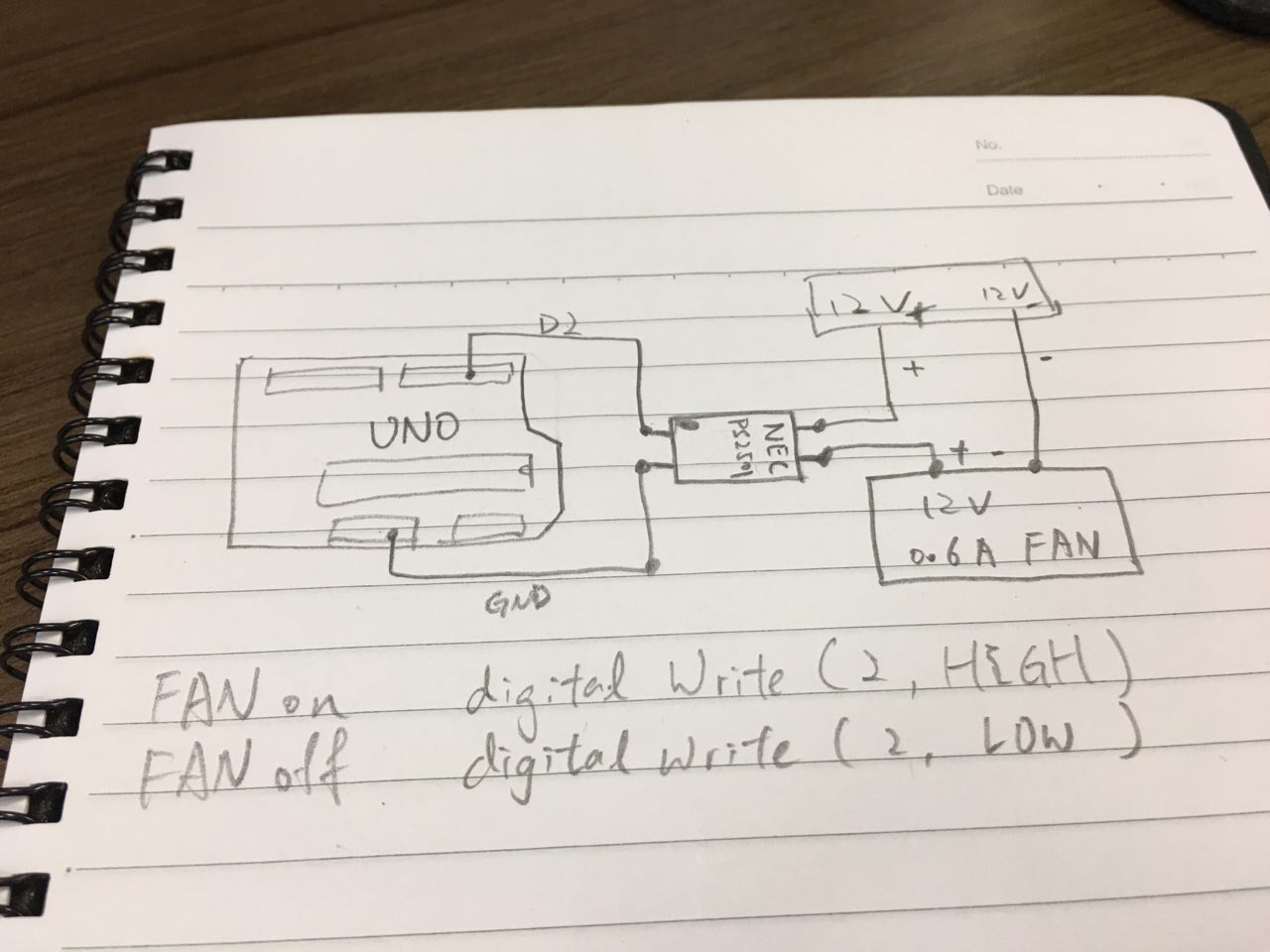
Hi Carson, me again. I had tried using following schematic to control the 12V FAN, but unfortunately the Fan just spins few seconds. Then have a noise but the fan not spinning.

R1: 1k ohm
analogWrite(3, 250);

Is there the resistor incorrect??
or just using digitalWrite(3, HIGH) instead of analogWrite() ?
or I need using analog pin for analogWrite() ?

Sorry for asking stupid question.

Your transistor is the wrong way around. Emitter needs to go to GND, Collector to the fan negative.

You probably destroyed the transistor by putting it into the circuit reverse.

Also, your fan might not like the PWM frequency and it may freak out the controller in it, so maybe analogWrite is not the way to go - or you need to change the PWM frequency to keep the fan happy.

// Per.

I just find I have 5 chips of ULN2803A in my drawer, therefore I would like to ask something about it.

How about using ULN2803A instead of photocoupler?

ULN2803A Key highlight:

  • 500-mA-Rated Collector Current (Single Output, sugguest: 300mA @ Page 11, Table 1);
  • GPIO: 5V (Fit for Arduino UNO)
  • Control: 12V - 50V (Fit for my 12V DC FAN)

Question for ULN2803A:

  1. Is it I need use 2 Channels (1B + 2B & 1C + 2C) for my 600 mA DC FAN?
  2. Could I connect 1B & 2B to Arduino UNO D2, D3 directly, no need any resistor?
  3. Could I connect 1C & 2C to DC 12V FAN directly, no need any diode?

Thanks.

ULN2803 not usable. Fan at 600ma loads exceeds 500ma maximum rated load of ULN2803. Any attempt to parallel outputs isn't likely to work.

Other suggestions were also incorrect like IRFZ44N. You need a logic level mosfet, one that turns on at 2.5 volts. Since you do not have a usable part and must purchase, get a logic level mosfet on a breakout board.

If you want bare part, here is one of thousands that will work:

avr_fred:
ULN2803 not usable. Fan at 600ma loads exceeds 500ma maximum rated load of ULN2803. Any attempt to parallel outputs isn't likely to work.

Refer to the datasheet (mention upper post), page 10 - figure 12, seems is can work with 2channels to enlarge the maximum rate load of ULN2803.

Or I am missing something? Thanks

With two channels and 600mA total, chip temp will be about 77C.
I leave calculation over to you.
Leo..

Wawa:
With two channels and 600mA total, chip temp will be about 77C.
I leave calculation over to you.
Leo..

datasheet, Page 11, section 9.2.2.3, Power Dissipation & Temperature.

Are you meaning I should use 4 or up to all channels to decrease the temperature?

But end of the page 11, datasheet said the IS's die juntion temperature to < 125 'C.

PS: Actually, I am not an Engineer, so I can't solve the these equations.

There is ~1.3volt (typical) left across the transistor switch when "on".
That results in 1.3volt * 0.6Amp = 0.78watt that has to be dissipated by the chip.
There is a thermal table in the datasheet that tells you the temp rise above ambient per watt.
I didn't say 600mA can't be done by that chip. It only will be hot.
Leo..