How to limit the amount of revolutions or counts the motor makes?

I am using a 12V DC motor with a quadrature encoder. I do not know the specs and neither do my colleagues. We have this project going on and we are using this old spare motor we have. What I am working on is designing this spool system that will be attached on the base of the robot, the spool itself should reel out a specific amount of wire controlled by either the revolution or the counts per revolution. I got a code, with PID as that's what we wanted, that reads the counts for continuous rotation in one direction depends on what I put in the code lines for that specific section. I am using a Pololu G2 High-Power Motor Driver 24v21 to drive the motor. Additionally I'd like to have something that'll be easy to turn it on and off and switch direction with i.e let's say press 5 on keyboard to start and 6 to stop when I read it from Python. So any help or ideas would be appreciated.

Keep in mind that I'd like to later on test it with Python as the robot runs on python, so I'll have to send data.

sketch_aug28_full.ino (3.21 KB)

sketch_aug26_encoder_counts.ino (1.06 KB)
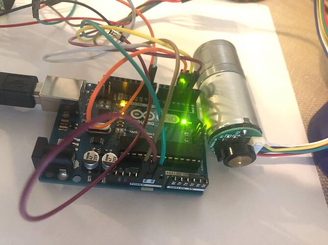
Please make your images visible in your Post so we don't have to download them. See this Simple Image Guide

For the same reason please include your code in your Post using the code button </>
codeButton.png

so your code 
looks like this

See How to use the Forum.

It would also be a good idea if you describe in as much detail as possible what happens when you run the programs, and what you want to happen that is different.

I can't figure what exactly you want help with.

...R

[/quote]

Robin2:
It would also be a good idea if you describe in as much detail as possible what happens when you run the programs, and what you want to happen that is different.

I can't figure what exactly you want help with.

...R

Sorry, this is my first time posting here. Thank you for the tips to improve my future posting.

So the sketch_full basically runs the motor continuously 360 degrees until I unplug the power supply and while it is running I am reading the encoder counts throughout the rotation. Nothing more than that. If I change the (dir,HIGH) to (dir,LOW) in the void loop and re-run it, it'll just read the counts and rotates the motor in the opposite direction.

The sketch_encoder_counts runs the motor from 0 up to the point where the pwm hits 255 and goes back down to 0. The counter works only for one rotation though, it cannot read the counts when the shaft changes directions.

Please post your program code in your next Reply - as requested in Reply #1.

Also please make the images visible.

...R

double count = 0; //set the counts of the encoder
double angle = 0;//set the angles
boolean A,B;
byte state, statep;

double pwm = 9; // this is the PWM pin for the motor for how much we move it to correct for its error
const int dir = 4; //DIR pin to control the direction of the motor (clockwise/counter-clockwise)

double setpoint = 360;//I am setting it to move through 360 degrees
double Kp = 0.32;
double Ki = 0.1;
double Kd = -0.3;

float last_error = 0;
float error = 0;
float changeError = 0;
float totalError = 0;
float pidTerm = 0;
float pidTerm_scaled = 0;// if the total gain we get is not in the PWM range we scale it down so that it's not bigger than |255|


void setup() {
  Serial.begin(9600);
  pinMode(2, INPUT);//encoder pins
  pinMode(3, INPUT);
  attachInterrupt(0,Achange,CHANGE); //interrupt pins for encoder
  attachInterrupt(1,Bchange,CHANGE); 
  pinMode(pwm, OUTPUT);
  pinMode(dir, OUTPUT);

}

void loop(){
  
  PIDcalculation();// find PID value
  
  if (angle < setpoint) {
    digitalWrite(dir, HIGH);// Forward motion
    
  } else {
    digitalWrite(dir, LOW);//Reverse motion
    
  }

  analogWrite(pwm, pidTerm_scaled);

  Serial.println(" WHEEL ANGLE: ");
  Serial.print(angle);

  delay(100);
}

void PIDcalculation(){
  angle = (0.9 * count); //count to angle conversion
  error = setpoint - angle;
  
  changeError = error - last_error; // derivative term
  totalError += error; //accumalate errors to find integral term
  pidTerm = (Kp * error) + (Ki * totalError) + (Kd * changeError);//total gain
  pidTerm = constrain(pidTerm, -255, 255);//constraining to appropriate value
  pidTerm_scaled = abs(pidTerm);//make sure it's a positive value

  last_error = error;
}
  
void Achange() //these functions are for finding the encoder counts
{
  A = digitalRead(2);
  B = digitalRead(3);

  if ((A==HIGH)&&(B==HIGH)) state = 1;
  if ((A==HIGH)&&(B==LOW)) state = 2;
  if ((A==LOW)&&(B==LOW)) state = 3;
  if((A==LOW)&&(B==HIGH)) state = 4;
  switch (state)
  {
    case 1:
    {
      if (statep == 2) count++;
      if (statep == 4) count--;
      break;
    }
    case 2:
    {
      if (statep == 1) count--;
      if (statep == 3) count++;
      break;
    }
    case 3:
    {
      if (statep == 2) count --;
      if (statep == 4) count ++;
      break;
    }
    default:
    {
      if (statep == 1) count++;
      if (statep == 3) count--;
    }
  }
  statep = state;

}

void Bchange()
{
  A = digitalRead(2);
  B = digitalRead(3);

  if ((A==HIGH)&&(B==HIGH)) state = 1;
  if ((A==HIGH)&&(B==LOW)) state = 2;
  if ((A==LOW)&&(B==LOW)) state = 3;
  if((A==LOW)&&(B==HIGH)) state = 4;
  switch (state)
  {
    case 1:
    {
      if (statep == 2) count++;
      if (statep == 4) count--;
      break;
    }
    case 2:
    {
      if (statep == 1) count--;
      if (statep == 3) count++;
      break;
    }
    case 3:
    {
      if (statep == 2) count --;
      if (statep == 4) count ++;
      break;
    }
    default:
    {
      if (statep == 1) count++;
      if (statep == 3) count--;
    }
  }
  statep = state;
  
}

Robin2:
Please post your program code in your next Reply - as requested in Reply #1.

Also please make the images visible.

...R

Done.

I like the simplicity of your PIDcalculation() function. Much clearer than the Arduino PID library.

Wouldn't it be much simpler to base your control system on pulse counts rather than converting the count to degrees? How many pulses are there per revolution?

I don't understand the use of state and statep. I thought the direction of the encoder could be obtained directly from reading the state of the two encoder pins?

Having said all that I can't relate your description of the problem "The counter works only for one rotation though, it cannot read the counts when the shaft changes directions."

Can you post some output from the program that illustrates the problem?

Is this code actually changing the direction?

 if (angle < setpoint) {
    digitalWrite(dir, HIGH);// Forward motion
    
  } else {
    digitalWrite(dir, LOW);//Reverse motion
    
  }

Add some print() statements so you can monitor it.

Doesn't the direction also need to change when the setpoint is exceeded?

...R

Robin2:
I like the simplicity of your PIDcalculation() function. Much clearer than the Arduino PID library.

Wouldn't it be much simpler to base your control system on pulse counts rather than converting the count to degrees? How many pulses are there per revolution?

I don't understand the use of state and statep. I thought the direction of the encoder could be obtained directly from reading the state of the two encoder pins?

Having said all that I can't relate your description of the problem "The counter works only for one rotation though, it cannot read the counts when the shaft changes directions."

Can you post some output from the program that illustrates the problem?

Is this code actually changing the direction?

 if (angle < setpoint) {

digitalWrite(dir, HIGH);// Forward motion
   
  } else {
    digitalWrite(dir, LOW);//Reverse motion
   
  }


Add some print() statements so you can monitor it.

Doesn't the direction also need to change when the setpoint is exceeded?

...R

Yes, the direction is depending on whether the dir pin is set on HIGH or LOW. That part of the code is actually not changing the direction, it keeps going. If I want to change the direction, I have to manually switch the HIGH to LOW.

My question should've been, sorry for not clarifying in the beginning - been a long week, now that I have this working I want to add in a few lines of code in this existing code that'll rotate the shaft 5-7 revolutions only and for me to be able to start/stop it and reverse with the press of a button on the keyboard.

I have been trying to find the pulses per revolution but I can't seem to get them with my codes. The codes I've used only reads the encoder counts as the shaft is rotating, I'd might have to mark it and time it manually as I have no specs of the motor except that it's 12V.

The final goal is to attach the motor to a spool so that I can reel in and out a line with a fixed # of revolutions.

Hope this clears it up a bit.

medodrbtbz:
Yes, the direction is depending on whether the dir pin is set on HIGH or LOW.

I was aware of that

That part of the code is actually not changing the direction, it keeps going. If I want to change the direction,

That was my question. If it is not changing the direction then that needs to fixed before you do anything else.

You did not respond to my final question in Reply #7 or my second question (in the 3rd paragraph.

Can't you turn the encoder by hand and get the Arduino to count pulses for one revolution? If you get approximately the correct number you can then refine it by getting the Arduino to run the motor slowly for several revolutions while counting pulses.

And another thought. You have this line in your PID function

pidTerm_scaled = abs(pidTerm);//make sure it's a positive value

I understand that the value for analogWrite() must be positive. But I think you also need to use the sign to set the motor direction so that the thing backs-up if it has gone too far.

Maybe that is where the direction change should be, and not where you have it now.

...R

Robin2:
That was my question. If it is not changing the direction then that needs to fixed before you do anything else.

Where would the change need to occur?

Can't you turn the encoder by hand and get the Arduino to count pulses for one revolution? If you get approximately the correct number you can then refine it by getting the Arduino to run the motor slowly for several revolutions while counting pulses.

Yes, I can do it by hand, but with one of the other codes that I have in my folder.

I understand that the value for analogWrite() must be positive. But I think you also need to use the sign to set the motor direction so that the thing backs-up if it has gone too far.

Maybe that is where the direction change should be, and not where you have it now.

Elaborate more on this please.

...R
[/quote]

medodrbtbz:
Where would the change need to occur?

I'm not sure what was in your mind when you wrote that. I have been assuming from what you said in Reply #8 and earlier that there is an error in your program. If so then you need to add suitable print() statements to monitor what is actually happening. However, as I said at the bottom of Reply #9 maybe you will conclude that you can just delete that piece of direction code.

Yes, I can do it by hand, but with one of the other codes that I have in my folder.

So how many pulses are there in a revolution?

Elaborate more on this please.

If you are using PID to cause the motor to stop and stay at a specific position then the PID code needs to be able to power the motor back and forth around that position - think of a guy on a unicycle who is not quite in balance.

...R

Robin2:
So how many pulses are there in a revolution?

47

It will be 48, not 47. Is that pulses or transitions (4 transitions per pulse for a quadrature encoder, you ideally count transitions for maximum resolution).

The way PID control of a motor works is that the output of the PID loop is a signed value. The sign sets the
direction, the absolute value sets the strength of the motor drive (ie passed to analogWrite).

The input to the PID is the difference between desired position and current position (encoder count). Thus you
need a variable that holds the desired position in encoder count units, and to change this programatically to cause a response. In the background (on a timer interrupt typically) the PID loop calculates and sets the motor
drive. Also in the background the encoder ISR maintains the current position variable.

For stablest loop the motor driver should be in synchronous rectification mode, failing that fast-decay mode, it should not be in slow-decay mode or you'll have little control of the motor