Hello people! I will be glad if you guys help me.
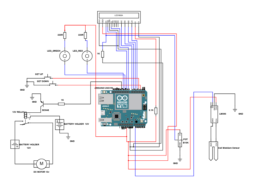
I have a problem with my irrigation system.Everything works fine ,the system measures the humidity,sends signal to Arduino ,turns on the relay and i am sure that everything is connected right.I had a problem with the backlight LED ,but i fix this.The main problem is when the relay goes on it closes the cirquit and the waterpump starts.After few seconds some kind of weird characters shows on the LCD and the only way to fix this is to reset the system.Does anyone know what probably is the incorrect may be in the code i dont know.I will send here the cirquit and check that i have a potentiometer 10k to Vo,Gnd and VDD,also i have a resistor before connection to anode A(to reduce the current-i was so close to damage the LCD ![]()
![]()
![]() ).
).
The materials are exactly the same like the schematics.
Don't post rubbish attachments! {attachments in .pdf form which is not compatible with viewing within Web pages}
Read the instructions for posting your code.
Provide a photo of your complete setup in detail, properly lit and a diagram of your connections.
Cite - web-links - the specifications of your parts other than the Arduino.
Explain the problem with your backlight.
Hello people.
I have written before about a problem with LCD weird characters.When the relay turn on the motor pump,some kind of strange charasters shows on the screen of LCD.I am sending you the code and schematic that i made.I hope that someone knows what i have to do and give me advise.
irigation_code.txt (2.4 KB)
Sounds like noise from the relay disturb the arduino and/or display. You should add a diode (1N400n) between the collector on the BC548 and +12V (direction: diode anode to 12 V) and see if that helps.
DUPLICATE POST MERGED
Please READ THIS POST for future reference and to get the best out of the forum.
Bob.
Thanks for giving me those advices.I will check that and if i have any problem again i will write again.
That's very strange! I was originally quite sure you posted the first image as a ".pdf" which is not really compatible with a Web page. We had a bit of fun with your cross-posting. ![]()
Here it is:

And the second:
So, you absolutely need that diode across the relay coil, and preferably, a similar diode across the motor itself for the same reason - to suppress switching impulses which can radiate into the microcontroller and display.
It will make it easier to set the contrast on the display if you do not connect the potentiometer to 5 V - this is an annoying and silly blunder that has been inherited since the early days. If you are using a 10k potentiometer, it is better to connect both ends to ground; a 1k with one end connected to ground would be the correct value. The 1k to ground in your first diagram is probably a little high. The correct setting depends on the actual value of your 5 V supply. ![]()
Another good idea is to put a 470 µF or so capacitor directly across pins 1 and 2 of the display.
Most "1602" displays have resistor "R8" on the board (or sometimes "R9" when R8 is zero) as "101" which is 100 Ohms and do not require any other resistor in series with the LED illumination supply (pins 15 and 16) except to dim it at night.
Those "moisture sensors" made of PCB are toys and will not last long. Two carbon rods out of old batteries would probably be more useful.
Don’t see the Arduino 0V pin going to a GND symbol.