Arduino-dht freeze, help make/select rc snuber, mov, caps to protect from 220v

I am an absolute beginner to state first! I'm a mechanic, not an electronic guy, but so far I learned some of the basics of AC and DC power, and let's say that now coding is my new schooling program.
Also I'm bit of tired as I'm trying to figure out this for almost a week and maybe I forgot to mention something but if I remember I'll add up :wink:
I can post my sketch if needed

Using:
Mega 2560
LCD 16x2
DS1307RTC
DHT22
4 channel relay with opto(not so great protection as I see now)

Made a working code for my greenhouse and now when I implemented everything, I found out that some of my components freeze arduino and/or dht when releys switch ON or OFF.

Relays are controlling next:

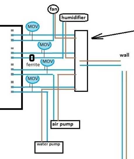
Duct fan 230V 0.11A(23W) 50Hz // also I made a dimmer(triac based), not sure if I can use it
Ultrasonic humidifier 220-240V 30W 50Hz
Small Air Pump 220-240V 2.5W 50Hz
Small Water pump 220-240V 2.5W 50Hz

and I have one more inline fan (230V, 14W, 50-60Hz) for just in case if it gets very hot to turn on manually and its connected on the same relay output where the other fan is, but so far I haven't used it in my setup (have separate switches after relays)

So far Humidifier works pefectly fine, switching it ON/OFF is fine, but then my first fan would crash LCD from time to time
Then we come to the bigger problem with air and water pump, which randomly switching on or off would freeze my arduino or sensor.

I measured spikes, I have a cheap multimeter, so I can say only what I saw and read.
With the use of 471 and 104 caps and 1N4001 diodes, I was able to lower spikes from 4.98V
to 5.00-5.04V (they went 5.10 and higher before)

Using PC PSU, MEGA is conected to 12V and relays to 5V rail, also I conected both grounds together.

What should I use here to sort this out? I found that one guy sorted this with using only ferrite rings, which I plan to add up too.
I was thinking about MOVs but need help to calculate values for it.
Also capacitor - snuber on AC side ? but dont know which one.

There's no need to show grounds since all grounds should be connected together. Same thing with the neutral wires on your mains- they should all be connected together, so no need to show every one of them. You only need one ground from the Mega- all others are redundant.

Your (almost) schematic shows you sending 12V AND 5V to the Mega?? One or the other, but not both.

What are the diodes supposed to do?

Other than the PSU, the Mega is completely separated from the motors, but depending on the quality of your PSU, that could be a vector for the voltage spikes. Also, when you describe voltages, spikes or otherwise, don't use relative values. Are you saying that your voltmeter would jump to 10V when the motors turn on? If that's the case, I would seriously look at the PSU.

Sorry, my mistake, I forgot to end up those two lines, it's where I measure voltage but no, the upper side of the board is 5psu and lower is from Megas 5v.

I tought diodes act in one way only, so I placed them so they can't backfire voltage back to Mega? or I misplaced something?

No, not at all that high, I was watching over the multimeter while alarm triggered one of the channels, and I saw a jump, when switched off, from 4.99 to 5.1V, not 10V

I forgot to ask, does it matter if it's actually 5.3V from PSU, and not round 5V ?

First thing, get rid of the ground wire from the MEGA to the relay module, it's not needed and may carry switching noise. The only connections between MEGA and relay module should be: 1 wire from MEGA 5V to relay Vcc and 1 wire from each MEGA output pin to a relay "in" pin. NO GND.
If you have the diodes in series the relay board is getting about 4.7V for power and 4.4V for signal.

Yes, this is one of those rare situations where removing a ground wire is beneficial. Your relay board will gain full opto isolation from the Arduino.

You'll need a suitable MOV (or snubber) connected across the switched contacts of each relay. This will greatly reduce interference and contact arcing and will prolong the life of the relays. Make sure the MOVs are rated for at least 275VAC continuous ... here's some possibilities.

I removed the ground wire and since my PSU share the same ground on 12V and 5V, I have used old 5V phone charger for relays
Arduino crashed again, but at least this time I could see LCD showing unreadable words and letters.

Now I wonder, can my sketch cause arduino to crash?

Vent.ino (4.73 KB)

The MOVs are really, really important.

Anyways, if you were controlling everything ... I would start by disconnecting all 220VAC load from all relays. Just get the low voltage DC components and sketch working first.

dlloyd:
Yes, this is one of those rare situations where removing a ground wire is beneficial. Your relay board will gain full opto isolation from the Arduino.

You'll need a suitable MOV (or snubber) connected across the switched contacts of each relay. This will greatly reduce interference and contact arcing and will prolong the life of the relays. Make sure the MOVs are rated for at least 275VAC continuous ... here's some possibilities.

Yes, I was thinking as well to get 275V with max of ~400V, but I don't know how much Farads do I need?
Also I was thinking of using metalized poly film cap of like 250V and resistor of 20-30ohms to make snubber, but I still don't know which capacity to use ?

Yes, I was thinking as well to get 275V with max of ~400V, but I don't know how much Farads do I need?

They're rated/sized mainly by voltage, current surge and energy. Any on that list provided should work fine.
You wouldn't need to make snuibbers if you use MOVs.

Yeah tested without AC now and I remembered that I already tested sketch a few times before I set everything up and connected to AC. I'm just a bit tired and already slamming my head for days to make this work.

Any recommendations for caps and resistors, considering I have low power consumers and as I will be on my way to the store in a few hours, so I'm thinking to pick a few of those while I'm there as some ferrite rings too

EDIT: I saw your msg before you edited. OK then and what about ferrite rings?

Yeah, the ferrite rings are also beneficial. You shouldn't need to worry about the caps and resistors.

Some things to consider:

Keep all AC wiring away from the DC circuitry.
Move the relay board away from close proximity to the Arduino MCU and other electronics.
Use a common point for grounding ... usually at the power supply.
Use a separate ground wire for each GND terminal, all connecting to the common point (star-point connection). Don't jumper from one GND to the next ... this will cause ground loops.

dlloyd:
Yeah, the ferrite rings are also beneficial. You shouldn't need to worry about the caps and resistors.

Some things to consider:

Keep all AC wiring away from the DC circuitry.
Move the relay board away from close proximity to the Arduino MCU and other electronics.
Use a common point for grounding ... usually at the power supply.
Use a separate ground wire for each GND terminal, all connecting to the common point (star-point connection). Don't jumper from one GND to the next ... this will cause ground loops.

Thank you for your advice. Wires are already separated and will move relays further away, when I add MOVs
I do that always, as I had previous experience in automotive with loose grounds :wink:

Here is a pic how it should look after and just to make sure I'm placing MOV and ferrite alright.

PS Don't confuse my bad paint skills, my wiring doesn't look like that, which may be the result of slight OCD :smiley:

Ideal relay board connections...

Four MOVs...

With the Mega powered at 12V, it may not be able to provide enough current for all the connected components. It will provide more current with a lower voltage supply, ideally 7.5V, or if not available, then 9V.

Yes, that's how the relay board is connected.
I was lazy to draw MOVs on all cables. . .
And ferrite goes after the MOV, on the side going to device.

I'll report my results back after setup and test.

The only other thing that I'm quite sure is an issue is the 12V supply. Here's why.

Using (1W / (Vin - 5V):
With 12V supply, you'll have about 142 mA available.
With 9.0V supply, you'll have about 250 mA available.
With 7.5V supply, you'll have about 400 mA available.

Approx Power requirements:
Mega: 70 mA
Relay Board: 60 mA
Other stuff (LCD display, etc) ?? mA <--- only 12mA remaining when using 12V at Vin!

Hey man, thank you very much, you are No1, I have readen other topics where you helped other people and I admire your knowledge, right on point :slight_smile:

I think we fixed crashing. I got 14n431k MOVs and ferrite rings and it worked a few times without any crashes.

Next thing I wanted to say is that my LCD is bothering me, it gets blank fields sometimes and it just might be what you have just said.

So as I got my 5V(5.3V) rail free on my PSU I can use it now to power Mega, should I go directly to Vin or should I use power jack?
Or should I stick strictly to 7.5V?
BTW I was then confused by the official statement, saying that you need from 6 to 12V to power you board, and I went for 12, as of thinking that more would be better, but now I see I was wrong

PS I got LCD16x2, RTC and DHT22 there too, and I plan to add up one or two more relays, but for controlling 12V power about 5A, maybe 10A max

You can use Vin or +5V pin (not both of course) or you could use the USB as an input to provide your 5V power.
If using the +5V pin, note that there will be no overload current protection.
If you use USB to provide the +5V, then this will take advantage of the on-board 0.5A polyfuse.

Hi,
Welcome to the forum.
Can you post a picture of your project so we can see your component layout.
Wiring layout is very important when using mains AC due to wiring interference.
Have you got your mains wiring away from any of the MEGA and its power supply wires.

Have you got fuses wired into the mains power inlet tot your project, or do you have one in the power plug, as in UK?

Tom... :slight_smile:

Hello
Yes, my wiring is separated AC from DC, in the pic, it might seem some are contacting each other, but actually small ones for VCC and signals are in the air not touching anything

I'm opting for power jack input then.

Also, this made me thinking what would be the next step of improvement in a similar setup, one set of relays just for control of the other set, with different power sources, like one would be only DC power, controlling AC on the other end?
Or there are just better and more expensive ones to go, and or what about SSR?
Some of my googling in past few weeks indicate that SSR is better, or it is dependant situation to control specific devices? Like where speed would matter?


idk if u can see img, here is it in code
img

Totally forgot about drop down on Vin and power jack sides, so it's directly to 5V.
This makes me worry a bit, do I need some capacitor on there or something for protection, considering it varies from 5.2 to 5.3V?

PS I forgot to answer in the previous post, only fuse is in the wall 10A

EDIT: I just found out that switching device off manually, after the relay, it would again cause a crash