Power Injection for 2812B LEDs

Hi,

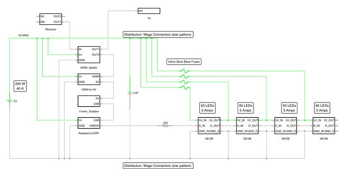
I'm building a TV Ambilight using a Raspberry Pi and 2812B LED strip. First draft schematic attached.

Few questions:

  1. I intend to keep the strip connected and bend them around the TV and solder power injection into all four sides. Should I cut the 5V trace (highlighted in yellow on the schematic zoom) where I'm adding power injection or leave them connected? What's the impact of this choice?

  2. Is it safe to daisy chain a few 5 lead Wago connectors for the power distribution?

  3. Similar to #2, is it safe to connect the resistor, capacitor, and inline fuses via Wago connectors?

  4. I'm planning on using 4 amp slow blow fuses on the 3 amp sections and 6 amp slow blow fuses on the 5 amp sections - is this appropriately sized?

  5. Is 18 AWG sufficient? I calculated the voltage drop and it's on the order of a few percent for the length of wire I'm running. I've read these LEDs exhibit the same brightness from ~4.2-5V

  6. Any concerns with powering the Pi, HDMI-to-AV, and HDMI Splitter from the same power source as the LEDs?

  7. Is the capacitor sizing and location sufficient/correct, or would you recommend adding a capacitor at each injection point?

Thank you!

Where is the Arduino in the project?

groundFungus:
Where is the Arduino in the project?

Where the Raspberry Pi is - as I may go that route when I box this all up in an enclosure.

Ambilight Circuit.png

Ambilight Circuit - Zoom.JPG

electricallyinclined:
Should I cut the 5V trace (highlighted in yellow on the schematic zoom) where I'm adding power injection or leave them connected? What's the impact of this choice?

Absolutely not. It is most important that you supply power to both ends of each LED strip. 50 LEDs will draw just under 3 Amps at full brightness white and the foil along the strip is very lightweight and will experience a significant voltage drop resulting in distorted colour so you need to inject power to flow in both directions along the strip every 50 or so LEDs and certainly at both ends for 85 LEDs.

electricallyinclined:
2. Is it safe to daisy chain a few 5 lead Wago connectors for the power distribution?

Probably - if they are rated for the current. I had to look up what "Wago connectors" are. :astonished: I think I have a couple here somewhere, perhaps not the genuine brand. :grinning:

electricallyinclined:
3. Similar to #2, is it safe to connect the resistor, capacitor, and inline fuses via Wago connectors?

If the wires fit. But should really be soldered.

electricallyinclined:
4. I'm planning on using 4 amp slow blow fuses on the 3 amp sections and 6 amp slow blow fuses on the 5 amp sections - is this appropriately sized?

Sounds appropriate.

electricallyinclined:
5. Is 18 AWG sufficient? I calculated the voltage drop and it's on the order of a few percent for the length of wire I'm running. I've read these LEDs exhibit the same brightness from ~4.2-5V

Maybe. But you do not want to combine voltage drop in the feeder wires as well as in the foil in the strip.

electricallyinclined:
6. Any concerns with powering the Pi, HDMI-to-AV, and HDMI Splitter from the same power source as the LEDs?

As long as the cables are adequate.

electricallyinclined:
7. Is the capacitor sizing and location sufficient/ correct, or would you recommend adding a capacitor at each injection point?

One millifarad (1 mF, often cited as 1000 µF) is correct but at the data input end of the strip, in fact one at the data input end of each strip (or at least, 470 µF) would be nice.

What is important is that the data connection from one strip to the next is accompanied - as a pair - by the ground connection from one strip to the next. Because you are feeding 5 V power back into the previous strip, you are actually going to have the 5 V power along as well.

In this respect, your diagram is misleading because it shows power and ground reticulated to the strips in different manners. It is particularly important that power and ground always travel as a pair - as does data and ground. You basically know that because that is how all the other cables run, your USB cable, your HDMI and "AV" cables always contain signal and ground together, but in the effort or putting in fuses and "star" distribution, you run the risk of overlooking it.

Note that this applies to the data from your Pi (or Arduino) - the data line must run with its matching ground from one component to the other. Because you have heavier wiring from the 5 V supply to the LED strips, it is actually sensible to run the 5 V power back along with the data and ground from LED strip to the microcontroller device.
Thanks for the response!

Re #1:

Paul__B:
Absolutely not. It is most important that you supply power to both ends of each LED strip. 50 LEDs will draw just under 3 Amps at full brightness white and the foil along the strip is very lightweight and will experience a significant voltage drop resulting in distorted colour so you need to inject power to flow in both directions along the strip every 50 or so LEDs and certainly at both ends for 85 LEDs.

Sounds good, however, if I'm powering from both ends, I have probably sized the fuses incorrectly. My ECE background has become hazy over time, and I don't have a schematic for the led strip which is complicating things. What's the best way to calculate current flow through each fuse at the IN and OUT of each strip?

Re #3 - soldering the wire and other components - are there any readily available general purpose PCBs/protoboards that can handle 20 amps that you recommend? I bought some breakout boards for the Raspberry Pi but I can't find a current rating so I'm not going to assume they can handle the current.

Re #7: Everything I've read has advised adding a capacitor on the supply voltage to protect against voltage variations, and a resistor on the data line for current limiting. Are you suggesting adding a cap on the data line instead, and if so why?

Re: data and ground travelling in pairs, I would be running pairs of wires to all the injection points from the distribution blocks (or PCB rails if I can find an appropriate one).

A cap on the data wire is bad. A cap would tend to smooth the pulses. That is the last thing that you want. I am sure that no one suggested that.

Indeed. What I said was "one at the data input end of each strip". That is, the end of the strip (because it has two ends) where the data input is, not at the data input. :grinning:

Well that makes a lot more sense :slight_smile:

Heard back from the breakout board manufacturer - only rated for 1.5 A.