I'm making a prototype using an arduino nano to control the temperature and the lights of my terrarium. So far the sketch is working as is the prototype itself.
For the prototype I was using components from the arduino starters kit.
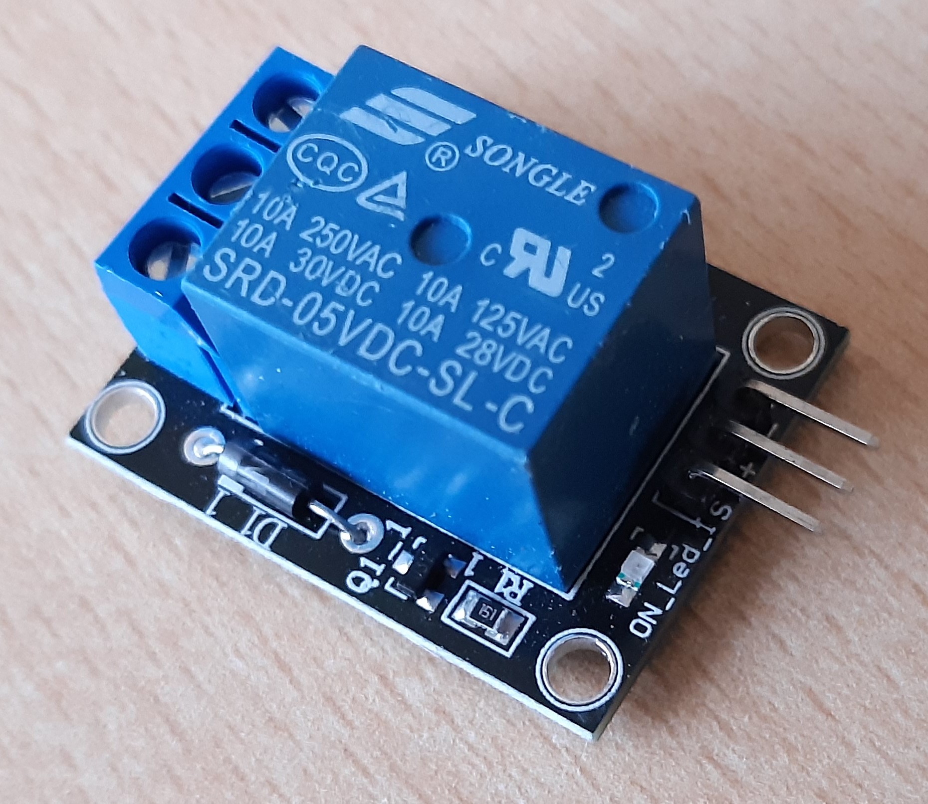
So far I was using the relay module from the starters kit which worked great. I connected it as followed:
= GND arduino
= 5V arduino
S = Port arduino
Now comes my problem. I ordered a new relay on the internet, a HL-52S dual channel relay module.
I connected it the same way is the relay from the kit. However the new relay doesn't respond, the led wont turn on and the relay won't switch. I connected the module like this:
GND = GND arduino
In1 = Port arduino
ln2 = Port arduino
VCC = 5V arduino
To troubleshoot I checked some tutorials and found that this setup should work..
Hopefully someone can tell me what I'm doing wrong?
Attached are two pictures of the relays I'm using. The first is the dual channel relay which isn't working. The second is the one from the arduino kit.
Can you post your schematic, it appears you are using the Arduino as a power supply which it is NOT! What else is connected to the arduino? What is the power source? How much current can it supply? If you can measure the 5V and see what it really is.
Thanks for responding.
First I powered the relay directly from the arduino indeed. For the single relay from the kit it wasn't a problem. The dual relay didn't work on the arduino so I tested it directly with a 5V 1A power supply.
When I put 5V from the power supply on ln1 or ln2 the relay doesn't do anything. Also does the LED not light up on the module
GND = - power supply
In1 =
ln2 =
VCC = 5V power supply
wildbill:
It's quite likely that you need to ground the relay inputs rather than giving them 5V.
It's not just "likely", it is absolutely certain!
These modules are "low level trigger". You need to write an Arduino output LOW to actuate the relay. And in your setup(), you need to write the pin HIGH before you set pinMode to OUTPUT to prevent the relay flicking on briefly when the Arduino boots.
Next, how to connect the module. Remove the jumper. Connect "JDVcc" and "Gnd" to + and - 5 V relay supply by a twin (figure 8 or ribbon pair) wire directly to the 5 V relay supply. Connect "Vcc" and the two "IN" connections to the Arduino (or ESP) 5V and corresponding control pins, again via a piece of ribbon wire. You do not connect "Gnd" to the Arduino as such (because the Arduino pulls the "IN" pins to ground). Here is the schematic so you understand:
Finally, make a point of never powering the Arduino via "Vin" or the "barrel jack". It may work if you have nothing more than a couple of LEDs with 20 mA current limiting resistors connected, but you have now discovered what the on-board regulator cannot do.
Connect regulated 5 V via the "5V" pin though on a UNO or Mega 2560 you need to disconnect this pin from power whenever you connect to a PC via USB. Not a problem with a Nano and once you start adding things like your relay module, it is the Nano that you should be using as the UNO is quite impractical for use other than with a matching "shield".