Sorry, I want to ask again. Are other components needed besides the laser module? because I only got the laser module, not with the other components.
I want to use it for Arduino, and there are 4 cables besides power. what are the uses of the cable?
sorry, I am still a beginner in using Arduino, and as soon as I am Arduino only use 2 cables (Tx and Rx) as data communication
Be aware this device interface is probably 3.3V so connecting a 5V Arduino to it may damage it.
As the picture shows the LDM connected directly to a BT module you should be good with UART signals (no need of RS232 adaptor board) as long as they are only 3.3V.
It looks like 2 wires from the battery pack go to power the LDM and then the 4 wires going to the BT module (HC-08) are going to be 3.3V (red), GND (black), RX (blue) & TX (grey)
Find the data sheet for your specific device. That will contain all the information needed on how to connect it (voltage level, power requirements, communication protocol, etc), and the specific commands to communicate with the thing (as that's the obvious next step).
It will also likely tell you what this Bluetooth module is doing. That probably offers another way of communicating with it. Could be more convenient than a wired connection.
Sorry for tearing up this old thread but I stumbled into the same pit as the Threadstarter.
I bought this part on Banggood and thanks to this thread I now know that it is manufactured by JRT.
That doesn't help much, though. I emailed them just now and asked if they could provide me the Datasheet and instructions, but I'd be surprised if they answered in a timely manner.
Here's some additional data from the Banggood listing:
Specifications:
Interface: 2.8V TTL signal .by PC show date. three wire serial interface ( the single chip microcomputer UART interface), 19.2 kHz.Start bit 1 + 8 + 1 stop bit and no flow contro
2 mA electrical flow: DC2.8V, standby, measuring 120 mA;
Laser type: 635nm, 1 mw.(red)
Range: 0.02 to 100 meters;
Measurement speed: 0.3-3 s
Typical accuracy: + / - 2 mm
Storage temperature: - 20-60 use temperature: -10-40
module size: Approx 724018mm
Communication and Control:
Communication interface: serial communication (TTL), 19.2K, baud rate parity bit: no parity, data bits: 8;
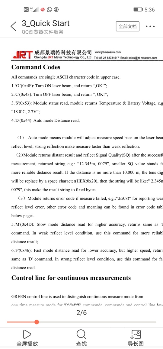
Function: send capital letters "O" to open the laser, capital letters "C" to close the laser, capital letters "D" for measuring distance, capital letters "S" to view the module temperature and power supply.
Instructions: open the laser, laser, a single measurement, gets to the power supply voltage and temperature.
There's some useful information there, but the main challenge is soldering the right ports.
I mean you can clearly see the + and - connectors, but where do I solder the cable which goes into the digitalPin?
I took a look at that version with the battery pack and I guess it could be the connector with the gray cable?
I'll post any info I (hopefully) receive from the manufacturer.
where do I solder the cable which goes into the digitalPin?
You need two connections to a serial port, to 3.3V RX and from 3.3V TX on a 3.3V Arduino.
In comparison to the radio module connections, it appears that on the laser module, the blue wire should be connected to Arduino TX, and the grey wire to Arduino RX.
The Lady from JRT said she wasn't entirely sure if the product from Banggood was the same as theirs, but she snapped some pictures of the manual with her phone (and sent me the screenshots )
They are low quality and cut off, but I've attached them for you guys.
In the coming days/weeks I'll try to make this work and report back if I succeeded!
Numbering the 8 pads inboard of the '+' pad 1 to 8:
pad 1 is B707B Rx and should be connected to Arduino Tx
pad 2 is B707B Tx and should be connected to Arduino Rx
And yes that seems to work just fine according to the codes given in above posts.
I used the attached sketch written by a friend to work for Teensy 3.6 Serial4.
All very simple and excessively obvious for some - but one has to start from somewhere.
Note that in using the IDE serial monitor, you will need to set the COM port to the speed set by Serial.begin
In the sketch it is the same as for the B707C but probably does not have to be.
There remains the mystery of what the other 6 pads on the B707C do.
One is probably to command a continuous series of measurements.
And, if you are excessively inquisitive, the other two connectors for flat ribbons. Probably for keypad and display in a handheld meter.
I should perhaps also add that if, having turned to aiming LED ON with an 'O', you then ask for a measurement with a 'D' or an 'M', the spotting LED is turned off as part of the B707C response.