I have a power supply for a project I am working on and I am fairly new to Arduino and electronics.
My Arduino Uno R3 (non-SMD) controls a transistor that controls a 5v relay that triggers a electronic door strike which is powered by a 12VDC power supply.
I was hoping to also power my Arduino off the same power supply using the Vin. I read that it supports 7-12V input and that 12V is not recommended as it will make the voltage regulator on the Arduino very hot if not burn up overtime.
I tested my 12VDC 3A power supply on Vin in hopes of not releasing the magical smoke inside, and everything works fine but the voltage regular does get extremely hot; well enough to burn my finger.
How would I go about taking this 12VDC 3A input and reducing it down to around 9VDC for the Arduino Uno R3 to handle more comfortably?
Grumpy_Mike:
I would take the 12V down to 5V and feed the Arduino with that on the 5V pin.
I would use a buck converter to get the 5V. Lots on line to choose from.
bawitdaba:
I was hoping to also power my Arduino off the same power supply using the Vin. I read that it supports 7-12V input and that 12V is not recommended as it will make the voltage regulator on the Arduino very hot if not burn up overtime.
In essence, the recommendation is not to use "Vin" or the "barrel jack" at all.
The on-board regulator is really a bit of a decoration. Its history is that it was really for demonstration use of the bare board back in the very beginning of the Arduino project when "9V" transformer-rectifier-capacitor power packs were common and this was a practical way to power a lone Arduino board for initial demonstration purposes. And even then it was limited because an unloaded 9 V transformer-rectifier-capacitor supply would generally provide over 12 V which the regulator could barely handle.
The Arduino runs on 5 V. So what you seriously need is a 5 V regulated supply, if you have 12 V, then one of the cheap and readily-available "buck" regulators from eBay and such is the most appropriate source, fed into the "5V" pin. Simple as that.
+1 on grump's solution. The onboard SOT-23 linear voltage regulator is relatively weak and only really good for running the arduino itself. Your best bet is to use a switching power supply that can give you higher current and better efficiency (lower heat).
Having said that if you run ONLY the Arduino using the 12V through Vin you should be fine. The Arduino itself will consume about 40-50mA. Even with 12V through the linear regulator it should cause negligible issues. The drop is only about 1/4 watts wasted with only the Arduino.
bawitdaba:
I was hoping to also power my Arduino off the same power supply using the Vin. I read that it supports 7-12V input and that 12V is not recommended as it will make the voltage regulator on the Arduino very hot if not burn up overtime.
If you don't draw any power from the Arduino for any other circuitry, it may be okay.
When I connect circuits to Arduino, I supply the circuit from a different power supply. I only connect Arduino ground with my circuit. I happen to be testing some bipolar PROMs that draw up to 100mA. I'm also using an HP548A logic clip to monitor all of the pins on the PROMs that can draw up to 50mA. They have their own 5V power source.
I tested my 12VDC 3A power supply on Vin in hopes of not releasing the magical smoke inside, and everything works fine but the voltage regular does get extremely hot; well enough to burn my finger.
You can decrease power dissipation in the on-board regulator by connecting any external circuitry to the Arduino power pins.
EDIT: Before anyone else feels the need to correct the above statement, I meant to say to "not connect to Arduino power pins".
How would I go about taking this 12VDC 3A input and reducing it down to around 9VDC for the Arduino Uno R3 to handle more comfortably?
You could use a voltage regulator or zener diode to reduce the voltage to 7-8V. But the power still needs to be dissipated. If you use a switching regulator, you can minimize dissipated power.
Many thanks to everyone for the replies, it's given me a lot to consider.
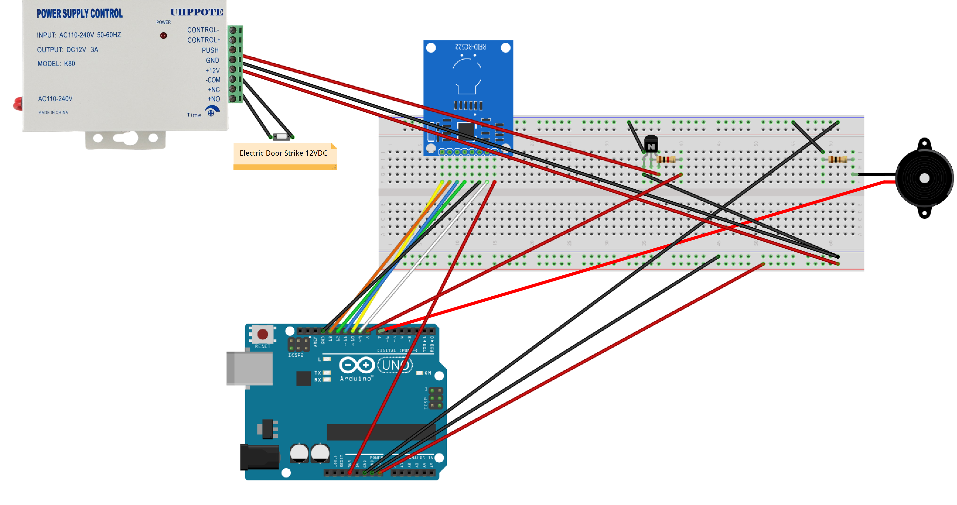
I spent a little time learning Fritzing and was able to re-create my project in this image.
I also wanted to include a link to my power supply as it is a little unusual, it's designed for Door Access control systems.
UHPPOTE Power Supply 110-240VAC to 12VDC for Door Access Control System & Intercom Camera
My main concern with all of this is really stability, this is going into a crawl space near a door and I don't want it to implode and catch fire for example.
My 2nd concern is trying to keep this stuff small and simple, I was planning on running all of the low voltage wires via Cat6 to the Arduino including 5v/12v supplies into a single/double gang box. (with a 2nd single gang box for high voltage 120vac)
Would it be possible to take a LN7805 for example and feed that directly into the 5v on the Arduino? I don't think that would be as efficient as a buck converter, but it would be much smaller and I could soldier that to a custom PCB with the transistor for the door strike.
It's hard for me to judge by looking at pictures of how big these buck converters are, do they make them small enough to fit into a single/double gang box for example?
bawitdaba:
Would it be possible to take a LN7805 for example and feed that directly into the 5v on the Arduino? I don't think that would be as efficient as a buck converter, but it would be much smaller and I could soldier that to a custom PCB with the transistor for the door strike.
Whoops!
You fail to understand the connection here. A 7805 dissipates the excess energy as heat. That straight away means it requires a heatsink That makes it much bigger than a switchmode buck regulator.
bawitdaba:
It's hard for me to judge by looking at pictures of how big these buck converters are, do they make them small enough to fit into a single/double gang box for example?
They are quite tiny. Go buy a few on eBay now.
Note: Do not attempt to build one yourself.
bawitdaba:
My main concern with all of this is really stability, this is going into a crawl space near a door and I don't want it to implode and catch fire for example.
Then you put it in a steel box.
dl324:
If you don't draw any power from the Arduino for any other circuitry, it may be okay.
Note that "drawing power" includes powering things connected to output pins, such as LEDs. A lot of LEDs at 20 mA each is quite significant to the on-board regulator.