8x16 Segment display driver with limited input

Hey guys,

First post here so I don't really know what I'm doing. Sorry, this will be really dumb but I really hope you can help!

So I pulled apart an old alarm clock. I pulled out the 7 segment display and I have been trying to figure out how to use it with an Arduino. Bottom line, I can't figure it out. The controller is TM1629A, the closest English data sheet I found is here. I also translated the actual Chinese one to English, so if you can be bothered that's here.

This is my sketch:

int clk = 8;
int data = 7;
int count = 0;
int temp = 0;
int raw[8] = {1,0,1,0,1,0,1,0};

void setup() {
  pinMode(clk, OUTPUT);
  pinMode(data, OUTPUT);
  pinMode(6, OUTPUT);
  digitalWrite(6, HIGH);
  Serial.begin(9600);
  //convert();
  //execute();
  Serial.println(raw[0]);
}

void loop() {
  handleSerial();
  delay(100);
  /*for(int i = 0; i < 8; i++)
  {
    Serial.println(raw[i]);
  }*/
  execute();
  delay(1000);
}

void handleSerial() {
  int check = 0;
  int incomingCharacter;
  for (int i=0; i< 8; i++) {
    while (check < 8) {
      incomingCharacter = Serial.read();
      if (incomingCharacter != -1) {
      //Serial.println(incomingCharacter);
      }
      if (incomingCharacter == 49) {
        raw[i] = 1;
        check++;
        break;
      }
      else if (incomingCharacter == 48) {
        raw[i] = 0;
        check++;
        break;
      }
      else if (incomingCharacter == 114) {
        check = 0;
        i = 0;
        Serial.println("Resetting... Done.");
      }
      delay(5);
    }
  }
}

void execute() {
  Serial.print("Sending: ");
  for (int i = 0; i < 8; i++) {
    //Serial.print(dat[i]);
    if (raw[i] == 0){
      digitalWrite(clk, LOW);
      delay(1);
      digitalWrite(data, LOW);
      digitalWrite(clk, HIGH);
      Serial.print("0");
    }
    else if (raw[i] == 1) {
      digitalWrite(clk, LOW);
      delay(1);
      digitalWrite(data, HIGH);
      digitalWrite(clk, HIGH);
      Serial.print("1");
    }
    else if (raw[i] != 1 && raw[i] != 0){
      Serial.println(raw[i] + " is an invalid character in string. Terminating...");
      break;
    }
    delay(50); 
    digitalWrite(data, LOW);
    delay(50);   
  }
  Serial.println();
  Serial.println("Success");
  Serial.println();
}

Essentially, using the serial moniter you can provide as many bytes as you like to send to the data pin of the controller. I've just been trying to send commands listed in the data sheet but it doesn't seem to do anything. I don't know if I have hooked something up wrong or is there a better way I could approach this?

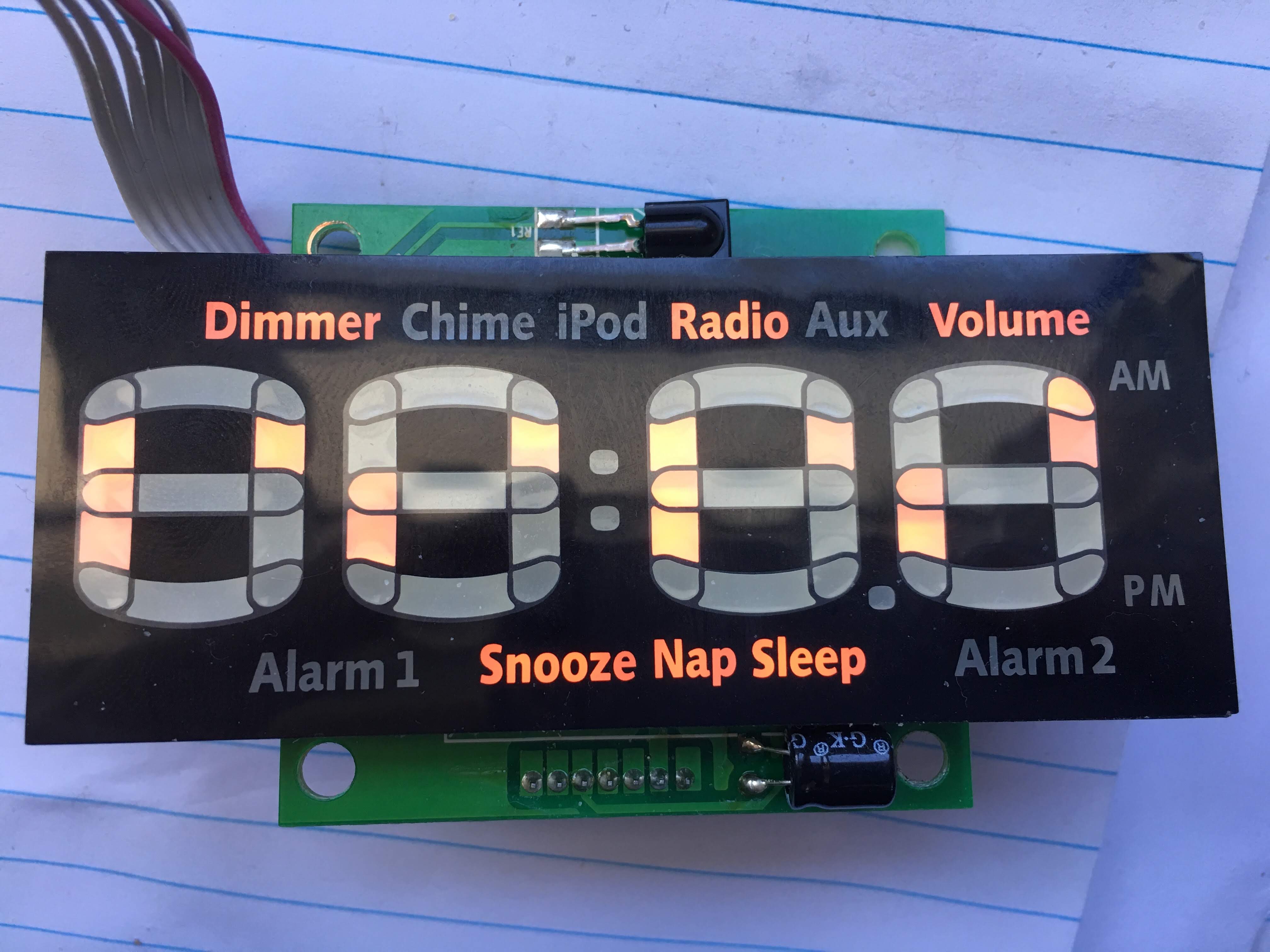
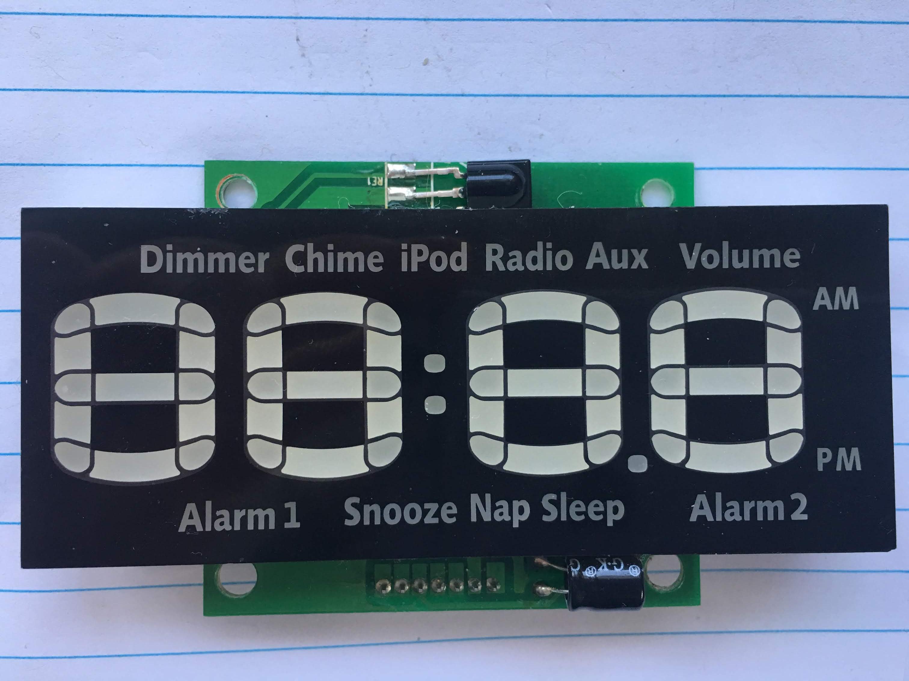
Here are a couple of images of the display and board: Imgur: The magic of the Internet.

In the second photo, the connections are labeled (not in picture) from left to right (top to bottom), VCC, GND, CLK, DAt, 3.3, CS, IR.
Out of these, I don't understand what the 3.3 (I guessed it just wanted a 3.3V input but idk) and CS pins are for.


I would like to learn how to turn on and off each segment.
If anyone could help me out at all, I'd be indebted to you. Thank you in advance! :smiley:

Please attach images to your post. We don't want to visit image sites full of adverts and possibly viruses.

Thanks for using code tags, but your thread title gives away that you did not read the forum guide, so please do that.

PaulRB:
Please attach images to your post. We don't want to visit image sites full of adverts and possibly viruses.

Thanks for using code tags, but your thread title gives away that you did not read the forum guide, so please do that.

My apologies, there were so many pinned threads I just skipped all of them. I was having issues with this sites image hosts, both uploading and viewing. It seems to be okay now.

JordanSmith:
there were so many pinned threads I just skipped all of them

I'm quite sure you are clever enough to work out which one I meant from the titles of those threads.

CS will be "Chip Select". Although the data sheet just calls the interface "serial", I suspect it is SPI compatible. Maybe they didn't want to say that to avoid having to pay money to anyone. SPI is a bus system that can connect the Arduino (the master) to several devices at once (slaves) using the same data and clock lines. Each slave will have a CS pin which the master will change to LOW when it wants to talk to that particular slave. So assuming you don't need to connect any other SPI slaves, you can connect that CS pin to ground.

As for the 3.3V pin, it could be an input or an output, it's not clear. There could be a 3.3V regulator on the board somewhere we can't see. Suggest you connect it to ground with 10K to begin with, connect Vcc & GND to 5V & 0V and measure the signal on the 3.3 pin. If it measures 3.3V, then perhaps there is a regulator on board. If it measures 0V, maybe you should connect it to 3.3V, but I don't know what for. The data sheet for the chip says it needs 5V. Maybe the IR receiver needs 3.3V.

PaulRB:
CS will be "Chip Select". Although the data sheet just calls the interface "serial", I suspect it is SPI compatible. Maybe they didn't want to say that to avoid having to pay money to anyone. SPI is a bus system that can connect the Arduino (the master) to several devices at once (slaves) using the same data and clock lines. Each slave will have a CS pin which the master will change to LOW when it wants to talk to that particular slave. So assuming you don't need to connect any other SPI slaves, you can connect that CS pin to ground.

As for the 3.3V pin, it could be an input or an output, it's not clear. There could be a 3.3V regulator on the board somewhere we can't see. Suggest you connect it to ground with 10K to begin with, connect Vcc & GND to 5V & 0V and measure the signal on the 3.3 pin. If it measures 3.3V, then perhaps there is a regulator on board. If it measures 0V, maybe you should connect it to 3.3V, but I don't know what for. The data sheet for the chip says it needs 5V. Maybe the IR receiver needs 3.3V.

I really appreciate your response. I have done what you suggested. For some reason I though CS had to be high but I believe you are right. I regret to say that I don't have an ammeter, so I cannot clarify the connection of the 3.3 pin, I'm hoping it is irrelevant, I had it plugged into 3.3V for a while and nothing changed. I'm not really interested in the IR. I assume it doesn't need to be connected to operate the display. There are no extra components on the board other than pictured.

I am thinking that my code might not be sending the data correctly? What I understand is if I send '01001100 11000000 10001000' (writing data test mode fixed address to display register, 00H address, display is on) a segment should turn on but nothing shows. Is there an issue with my clock timing?

Just, if you want it for more information, there is an image of the main board. The connection working with is in the bottom left corner.

Edit: I did as you said but used an individual LED in series. On 3.3V no connection lit up but with 5V on the 3.3 pin every connection lit up the bulb. I don't know what to make of that.

Update: found this which works (soz for the link u can use a search engine to find if you like just search 'TM1628 Arduino library' first link) GitHub - BlockThor/TM1628: Control the dvd's LED display with IC TM1628 by Arduino. This is the most progress I've had being able to turn some segments on and off. However, I don't have precise control over which because my display isn't the same size as what the library was written for? any help here?

I have a few requests in return for any help I can give.

Don't quote entire posts when you respond, it just makes the whole thread longer but adds nothing. If you want to quote something specific, just quote that part. If not, use Reply instead of Quote.

Please learn to attach your own pictures to your posts. It's a little awkward. You have to attach them and post, as you have done, but then copy the address of the image, edit the post, hit the insert image icon and paste the address.

Edit: I did as you said but used an individual LED in series. On 3.3V no connection lit up but with 5V on the 3.3 pin every connection lit up the bulb. I don't know what to make of that.

I don't know what to make of that entire paragraph. I read it several times. Can you explain again using more precise terms, avoiding any possible ambiguous interpretations? Thanks.

My apologies, thanks for the advice. I have followed what you said.

PaulRB:
I don't know what to make of that entire paragraph. I read it several times. Can you explain again using more precise terms, avoiding any possible ambiguous interpretations? Thanks.

I don't have an ammeter so I connected the 3.3 pin to 3.3V and used another wire connected to ground to test which pins were actually connected. As you said their would either be 0V or 3.3V so I don't need to know the exact voltage, but only if there is a voltage. Using the LED I can see when the circuit is closed or open. When supplied with 3.3V all connections cause the led to (VCC CLK DAt CS or IR) light up but very dimly, almost unnoticeably so I'd guess it would read 3.3V.

Using this sketch

#include <TM1628.h>
// define - data pin D9, clock pin D8 and strobe pin D7
// обьявление портов: DIO - порт D9, CLK - D8, STB - D7
TM1628 dvdLED(9, 8, 7); 

void setup() {
  dvdLED.begin(ON, 2);
  dvdLED.print(8888);
}

void loop() {
    
}
/* sequence of LEDs:
   порядок светодиодов:
    LED_SE0 0x00
    LED_SE1 0x01
    LED_SE2 0x02
    LED_SE3 0x03
    LED_SE4 0x04
    LED_SE5 0x05
    LED_SE6 0x06
    LED_SE7 0x07
    LED_DVD 0x08
    LED_VCD 0x09
    LED_MP3 0x0A
    LED_PLY 0x0B
    LED_PAU 0x0C
    LED_PBC 0x0D
    LED_RET 0x0E
    LED_DTS 0x0F
    LED_DDD 0x10
    LED_CL1 0x11
    LED_CL2 0x12
*/

I get this output:

This display operates without the ground pin connected??? how?

The return current must be finding a way back to the Arduino through one of the other wires. This is not a good thing, damage could be happening. Always connect the ground wire. I would connect 5V to Vcc and if the display works without it, leave 3.3 pin unconnected.

Did you see this?

PaulRB:
Did you see this?

Yes, I did come across that article. I sent an email to Vasyl asking for help, awaiting a reply.

Using his library, I got the output in the image above. I realize I didn't explain it very well. I can't generate a readable display. It all seems random, I am yet to find a pattern but I believe the dimensions of my display are different from what the library was originally written for.

Any insight for this issue? I'm thinking I could I possibly rewrite the library for my borad but I am still trying to understand it, I am a newbie.

Edit: I orgininally had the TM1629 library from here: GitHub - BlockThor/TM1628: Control the dvd's LED display with IC TM1628 by Arduino. The library attached to that article doesn't seem to do anything to my display. I don't know if I'm using it wrong though, I just copied the sketch straight into IDE, it didn't do anything.

Edit 2: I had the pins incorrectly defined. I got it to work but I have the same issue. This library is easer to understand for me but I don't know how to edit it so I can use it. This is the output of the sketch from the site you linked.

The problem here, as you figured out, is that both libraries you tried were designed for tms1629 used with a particular display, neither of which is like your display. Neither library is generic/flexible enough to drive an arbitrary display without needing to be altered. You have the added difficulty of not knowing the pinout of your display, or how it is wired to the chip. It's going to take some skill and determination to reverse engineer that and adapt the library. Oh, and a multimeter. Just a cheap £10 one will be good enough for 95%+ of projects.

PaulRB:
You have the added difficulty of not knowing the pinout of your display

Sorry, what do you mean by that?
What logical method would I need to take to solve this?

You have no data sheet for the display, which would tell you what pins are connected to which anodes & cathodes. You could unsolder it from the board and test it to work that out, but you would also need to know which pins on the tms chip they are connected to, so it's probably no easier than other methods.

Suggest you write a test sketch to light one segment of one digit at time and methodically work out how segments are wired to the chip. Which is where you started out, but that sketch was too simple, I guess.

I think those libraries have a buffer[] array and an update() method/function which could be used to light a single segment, so maybe try using those in a new test sketch.

PaulRB:
You have no data sheet for the display, which would tell you what pins are connected to which anodes & cathodes. You could unsolder it from the board and test it to work that out, but you would also need to know which pins on the tms chip they are connected to, so it's probably no easier than other methods.

OKay, I have been able to determine the GRID pins are all anodes and the SEG pins are all cathodes, I can light each segment up but touching 5V and GND to them in combinations.
At this point, the best solution I can see is wiring each GRID and SEG to an individual pin and just set them high and low, simply from a lack of a better option(obvs not gonna do this idek how I'd do the gnd pins).

I would like to be able to use the data pin I don't know what information to actually send to the chip to tell it what I want it to do.

This is what I am struggling to understand.


What is 00HL? I thought they were addresses but I can't write to them, or at least I don't know how to. How can there be a single one for four segments?

I don't know how it operates. I mean, I don't really know what the code does. I interpret it the best I can but I get confused because I don't have a lot of experience with microprocessors the code isn't commented. I came to this forum because you guys know what you're doing! I have been trying different things but I think I need to edit this from TM1628ts.h (https://github.com/onetransistor/arduino-libraries/tree/master/Display_Segment/TM1628ts)
If anyone could skim over that ^^ and give me any ideas I would be very grateful because I'm lost.

const unsigned char tm_digit[18] = {0x7e, 0x48, 0x73, 0x6b, 0x4d, // 0, 1, 2, 3, 4
                                    0x2f, 0x3f, 0x68, 0x7f, 0x6f, // 5, 6, 7, 8, 9
                                    0x7d, 0x1f, 0x36, 0x5b, 0x37, 0x35, // A, b, C, d, E, F
                                    0x01, // minus sign
                                    0x65 // degree sign
                                   };

 byte tm_buffer[14] = {0x00, 0x00, 0x00, 0x00, 0x00, 0x00, 0x00, 0x00, 0x00, 0x00, 0x00, 0x00, 0x00, 0x00};

Update:

I have determined the anode connections include(segments from right to left of the display):
GRID1 - Second segment
GRID2 - First segment
GRID3 - third segment
GRID4 - fourth segment
GRID5 - Utility
GRID6,7,8 - N/C

and the cathode connections:

Seg 11 o---Seg10---o Seg 9
| |
| | Seg 8
| |
Seg 2 o---Seg4---o Seg 16
| |
Seg 1 | | Seg 15
| |
Seg12 o---Seg3---o Seg 14

The top left segment is connected to grid5. Sorry, just documenting this here for my own purposes.

Why are you reading the data sheet for tms1651? Your chip is tms1629. The table you show should have been this one, I think:

Yes, I understand the difference. I just picked out a smaller table that seems to reflect the same information. I don't know what it represents though, does that help me at all?

I think this thread is better suited to the programming topic. When I first posted this, I didn't know how the microprocessor operated. But now I don't know how to program it.

Don't just pick out parts of the wrong data sheet. You risk confusing us, or at least making us think you are so confused that its hopeless trying to help you.

The table seems to show the memory registers inside the chip which control the segments of the display. I don't know why the data sheet author makes it seem so complex with all the "00HU" designations, they don't help to make things clearer, in my opinion. Basically there are 8 x 16-bit registers to control up to 8 digits with up to 16 segments per digit. However, the data is read/written in bytes, so each 16-bit register has two consecutive addresses.

How you write to them must be explained elsewhere in the data sheet. There must be some way for the microcontroller to send an address, then send the data to be written to that address.

The problem here is that manufacturers wire the display to TM1629 (and similar) controllers the way they want.

From datasheet:

"The storage of this register is transferred from external component to TM1629 through serial
port, with an address of 16 bytes unit in total from 00H-ODH, corresponding to the LED lamps
connected to the chip’s SGE and GRID pin respectively. "

Display RAM is 16 bytes only. 16x8 = 128 bits. Make an empty buffer of 16 bytes and send it to TM1629 using its interface. Then take each byte in a loop and set each of its bits in another loop. Send the buffer to TM1629. Print what byte and bit you are setting on Arduino serial monitor and add a sufficient delay.

Take a pen and paper and draw the segments of your display. When they light up (one at a time), write the byte and bit next to each of them. You will soon notice a pattern.

Maybe every byte holds the bits for the same segment of each digit. Or maybe every byte's bits control a single digit. It's likely that not all buffer data is used.

It's not as hard as it seems to do it and this is the only way. This is how I wrote the libraries for TM1628, SC75823 and HT16515 (https://github.com/onetransistor/arduino-libraries/tree/master/Display_Segment). There's no other way when you can't find a schematic of the module and display.

Thank you so much for the reply, I really appreciate that! I'm so close to being able to control 100% of the display now!

I went through your library and a few similar ones from other publishers. I really struggle to understand them. This is the first microprocessor I have attempted to repurpose. I thought that being a simple display I wouldn't have too much trouble with it. I was wrong.

I assume you read this, but for reference, I'll leave it here.

I determined the anode connections include(segments from right to left of the display):
GRID1 - Second segment
GRID2 - First segment
GRID3 - third segment
GRID4 - fourth segment
GRID5 - Utility
GRID6,7,8 - N/C

and the cathode connections:

Seg 11    o---Seg10---o       Seg 9
             |                         |
             |                         |       Seg 8
             |                         |
Seg 2      o---Seg4---o       Seg 16
             |                         |
Seg 1    |                         |       Seg 15
             |                         |
Seg12     o---Seg3---o       Seg 14

The top left segment is connected to grid5, strange.

OneTransistor:
Take a pen and paper and draw the segments of your display. When they light up (one at a time), write the byte and bit next to each of them. You will soon notice a pattern.

Okay, I have done this. I am building off your TM1628ts and I've been using disp.putDigitAt(). I have edited the block of information in your .h file to:

const unsigned char tm_digit[32] = {0x00, // All off
                                    0x04, 0x08, 0x10, 0x20, 0x40, // one segment 0,1,2,3,4,5
                                    0x44, 0x48, 0x50, 0x60, 0x24, 0x28, 0x30, 0x14, 0x18, 0x0C,// two segments
                                    0x4C, 0x54, 0x64, 0x68, 0x70, 0x34, 0x38, 0x1C, 0x58, 0x2C, // three segmenents
                                    0x78, 0x74, 0x6C, 0x5C, 0x3C, // 4 segments
                                    0x7C // all on
                                   };

 byte tm_buffer[16] = {0x00, 0x00, 0x00, 0x00, 0x00, 0x00, 0x00, 0x00, 0x00, 0x00, 0x00, 0x00, 0x00, 0x00, 0x00, 0x00};

I realized what you had been doing in the block. Knowing this I applied it. Being 8x16 system I must be trying to write with a single byte to specify the desired grid pin (might be obvs for u soz :P). With trial and error, I was able to discover the important bits to store (01111100 the '1's in the byte correspond to grids 1-5 so 01111100 would light the chosen segment of all 5 grids). and I changed the buffer to 16 as you said. This drastically improved the ability to display segments for me!

So I have the Grid pins, sorted but I'm stuck with the segment pins. Your library was initially written for 7 segments but I have access to 16. My issue is that I can only go up to segment 7. Something in your code is locking me out from going any higher than 7, no error message, just a blank output. I feel a solution to this should be as simple as changing a 7 to a 16 somewhere.

I tried editing the function to fix this, with no prevail:

void TM1628ts::putDigitAt(byte digit, int pos) {
	for (int i = 0; i < 7; i++)
		bitWrite(tm_buffer[i * 2], pos, bitRead(tm_digit[digit], 6 - i));
}

For further clarification, I have access to the first 8 (0-7) segments but I am clearly missing 8 segments (8-16). This is an image of all LEDS I can illuminate at this point. Focusing on the first digit you see the top left, top middle, top right, right, lower right, bottom right, bottom middle and bottom left are uncontrollable. I have 8 segments missing.


This is the full program which displayed that image:

  const unsigned char tm_digit[32] = {0x00, // All off 0
                                      0x04, 0x08, 0x10, 0x20, 0x40, // one segment 1-5
                                      0x44, 0x48, 0x50, 0x60, 0x24, 0x28, 0x30, 0x14, 0x18, 0x0C,// two segments 6-15
                                      0x4C, 0x54, 0x64, 0x68, 0x70, 0x34, 0x38, 0x1C, 0x58, 0x2C, // three segmenents 16-25
                                      0x78, 0x74, 0x6C, 0x5C, 0x3C, // 4 segments 26-30
                                      0x7C // all on 31
                                     };

  byte tm_buffer[16] = {0x00, 0x00, 0x00, 0x00, 0x00, 0x00, 0x00, 0x00, 0x00, 0x00, 0x00, 0x00, 0x00, 0x00, 0x00, 0x00};
  
int tm_dio = 9;
int tm_clk = 8;
int tm_stb = 7;

void setup() {
  Serial.begin(9600);
  init(2);
  // put your setup code here, to run once:
}

void loop() {
  clearBuffer(-1);
  writeBuffer();
  for (int i = 0; i < 16; i++){
    putDigitAt(31, i);
  }
  writeBuffer();
  delay(100000);
  }


void init(int intensity)
{
  pinMode(tm_dio, OUTPUT);
  pinMode(tm_clk, OUTPUT);
  pinMode(tm_stb, OUTPUT);

  digitalWrite(tm_stb, HIGH);
  digitalWrite(tm_clk, HIGH);

  delay(200);

  tm_sendCommand(0x40); // command 2

  digitalWrite(tm_stb, LOW);
  tm_sendByte(0xc0); // command 3
  for (int i = 0; i < 16; i++)
    tm_sendByte(0x00); // clear RAM
  digitalWrite(tm_stb, HIGH);

  tm_sendCommand(0x03); // command 1

  setIntensity(intensity);
}

void setIntensity(int intensity)
{
  if (intensity < 0)
    {
      tm_sendCommand(0x80); // command 4
      return;
    }

  tm_sendCommand(0x88 | (intensity % 8)); // command 4
}

void putDigitAt(byte digit, int pos)
{
  //if ((pos < 0) || (pos > 7))
    //return;

  for (int i = 0; i < 7; i++)
    bitWrite(tm_buffer[i * 2], pos, bitRead(tm_digit[digit], 6 - i));
}

void clearBuffer(int pos) {
  if (pos == -1)
    {
      for (int i = 0; i < 16; i++)
        tm_buffer[i] = 0x00;
      return;
    }

  if (pos >= 8)
    return;

  for (int i = 0; i <  8; i++)
    bitWrite(tm_buffer[i * 2], pos, 0);
}

void writeBuffer()
{
  tm_sendCommand(0x40); // command 2
  digitalWrite(tm_stb, LOW);
  tm_sendByte(0xc0); // command 3
  for (int i = 0; i < 16; i++){
    tm_sendByte(tm_buffer[i]); // set RAM
  Serial.println(tm_buffer[i]);
  }
  digitalWrite(tm_stb, HIGH);
}

void tm_sendCommand(byte data)
{
  digitalWrite(tm_stb, LOW);
  tm_sendByte(data);
  digitalWrite(tm_stb, HIGH);
}

void tm_sendByte(byte data)
{
  for (int i = 0; i < 8; i++)
    {
      digitalWrite(tm_clk, LOW);
      digitalWrite(tm_dio, data & 1 ? HIGH : LOW);
      data >>= 1;
      digitalWrite(tm_clk, HIGH);
  }
}

@OneTransistor, you're my best hope at figuring this out! Any insight?