SPI MOSI Output less than 1V

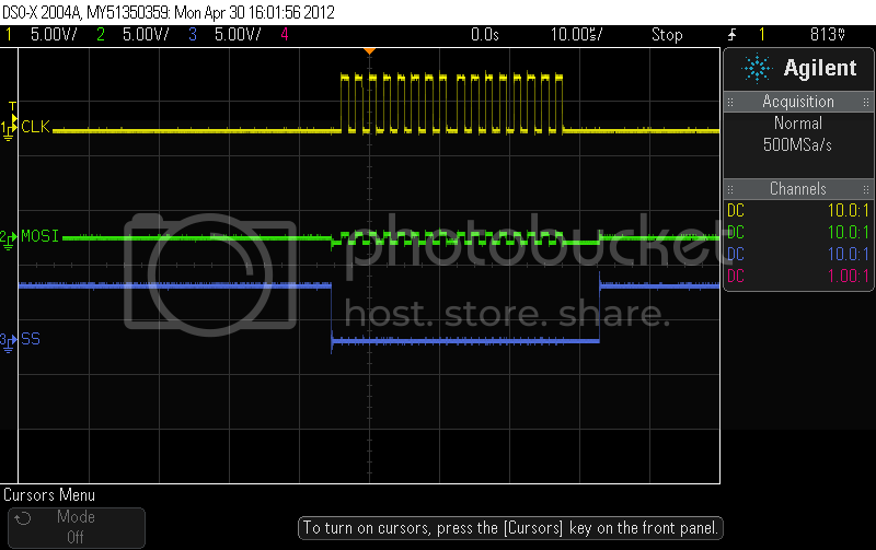
I am trying to communicate with a AD9834 DDS, after banging my head against the wall all weekend I connected the SPI lines to the scope and found that the MOSI line is outputing less than 1V P-P. See image. I have checked my probes they are all 10:1 and set correctly in the scope. I have tried not initializing MOSI, SS, and SCLK and I have tried initializing them. I have set there state and then initialized and then vice versa, still nothing. I have tried with the AD9834 connected and disconnected also, to no avail.

Also, ive tried with different ATMEGA328's and still have had no luck.

I have also tried running the code once in the setup, and then I have tried in the main loop with an if statement.

I should note that this is my first time using SPI and there may be something totally obvious im missing.

Any help?

#include <SPI.h>

int i =0;
void setup() {
Serial.begin(9600);
SPI.begin();
SPI.setClockDivider(SPI_CLOCK_DIV32);
digitalWrite(SCK, LOW);
digitalWrite(MOSI, LOW);
digitalWrite(SS, HIGH);
pinMode(SCK, OUTPUT);
pinMode(MOSI, OUTPUT);
pinMode(SS, OUTPUT);
//pinMode(ss, OUTPUT);
//pinMode(11, OUTPUT);
//pinMode(10,OUTPUT);
//hpinMode(13,OUTPUT);
SPI.setDataMode(SPI_MODE1);
SPI.setBitOrder(MSBFIRST);
delay(100);

Serial.println("Initilized");
}

void loop() {
if(i <2){
delay(100);
digitalWrite(SS, LOW);
//delay(50);
SPI.transfer(0x21); //Write MSB to control reg
SPI.transfer(0x00); //Write lsb to control register
digitalWrite(SS, HIGH);
delay(10);
digitalWrite(SS, LOW);
//delay(50);
SPI.transfer(0x50);
SPI.transfer(0xC7);
SPI.transfer(0x40);
SPI.transfer(0x00);

// digitalWrite(SS, HIGH);
delay(10);
//digitalWrite(SS, LOW);
SPI.transfer(0x82);
SPI.transfer(0x7E);
SPI.transfer(0xBE);
SPI.transfer(0x3F);

// digitalWrite(SS, HIGH);
delay(10);
//digitalWrite(SS, LOW);
// delay(50);
SPI.transfer(0x20);
SPI.transfer(0x00);
digitalWrite(SS, HIGH);
i++;
Serial.println("In if");
//delay(100);
// put your main code here, to run repeatedly:
}
delay(10);
//Serial.println("loops!");

}

Maybe it is just me, but aren't those channels set to 5v/div? That is what it implies at the top of the display. If so, and you do have the probes set to 10:1, you have 50vdc on the MOSI and the SS pins as they cycle.

It appears the CLK is set to 10:1 and AC.

Hi Tim,

I understand what your saying, but the scope takes probe attenuation into account and scales the display accordingly. So they are correct, and I'm getting 5V output on the SCLK and SS. If you look at the bottom right you can see that delta Y (2) (channel 2) is 625mV.

I see 5v on MOSI (ch1) and SS (ch3). Channel 2 is the clock, and it is the one not up to par.

BTW, I can't see the numbers on the channel delta values. It is cut off on my browser.

Whoa, good catch I labeled the channels incorrectly. Fixed it now.

I would have suggested that the pinMode()s and digitalWrite()s here were interfering with the SPI.begin() and totally unnecessary, and to take them out.

But since you appear to have it working ...

SPI.begin();
SPI.setClockDivider(SPI_CLOCK_DIV32); // this line is okay

digitalWrite(SCK, LOW); // not needed
digitalWrite(MOSI, LOW); // not needed
pinMode(SCK, OUTPUT); // not needed
pinMode(MOSI, OUTPUT); // not needed

pinMode(SS, OUTPUT); // needed still
digitalWrite(SS, HIGH); // and move to after you define it as an output

Hi CrossRoads,

I have yet to get the SPI link working, my error was in my scope capture, I had mislabeled MOSI and SCLK, but its still not working. My output voltage is still 650mV.

Initially I was only using pinMode() and digitalWrite() for the Slave Select line, and I still had the same issue. After searching around I had found an article where the author mentioned that the SPI library had issues with data modes other than "SPI_MODE0". The article mentioned something about trying to initialize them and I did, which didnt help. Same goes for the order of write and define, it was something mentioned on the article I read.

Thanks for your help!

Have you tried just toggling the offending pin without SPI to prove that the pin is not buggered?


Rob

Hi Rob,

I have not tried toggling the offending pin, I will try that tomorrow AM. I have tried two separate arduinos and have had no success. If they are buggered I wonder if the AD9834 is somehow trashing the MOSI?

Another thing I noticed is that I am not seeing Data on the MOSI pin, I believe that I am seeing cross talk from the SCLK line since the signal is the same as SCLK but at a reduced amplitude. It appears that im actually not getting any output from the MOSI pin.

Thanks

CrossRoads:
pinMode(SS, OUTPUT); // needed still
digitalWrite(SS, HIGH); // and move to after you define it as an output

..also not needed. SPI.begin takes care of it...

https://github.com/arduino/Arduino/blob/master/libraries/SPI/SPI.cpp#L15

Cool - didn't realize SS was taken care of. Had been putting that in all my programs. Can shave a few bytes out of void setup.

Thanks,

One thing i'm curious about and I cant find any info on is if the MOSI pin is Push Pull? I'm assuming it is and that I dont need any pull ups?

Another thing i'd like to confirm, is that for a 3-Wire SPI system with arduino Master, the SPI slave should be connected to the MOSI and not the MISO of the arduino? Currently I have arduino MOSI connected to AD9834 SDATA. I believe this is correct, that the arduino will be sending data out over MOSI.

http://www.analog.com/static/imported-files/data_sheets/AD9834.pdf

tanky321:
One thing i'm curious about and I cant find any info on is if the MOSI pin is Push Pull?

Correct.

I'm assuming it is and that I dont need any pull ups?

Correct.

Series resistors (I use 220 ohms) are a good idea until you've worked out the kinks.

Yes, pullups are not needed with the SPI pins. 0/5V outputs.

Yes - Master Out, Slave In (MOSI). Arduino MOSI to slave's Data-In.

and
Master-In, Slave Out (MISO). Arduino MISO to slave's Data-Out.

For the other stuff, I'll get back to you after looking at the datasheet. Unless someone beats me to it.

In the meantime, maybe this will help...

MOSI is Master Out Slave In. This line is data leaving your Arduino (the Master) destined for the AD9834 (the Slave).

MISO is Master In Slave Out. This line is data leaving the AD9834 (the Slave) destined for your Arduino (the Master).

SCK is always controlled by the Master.

Argh! Ninja'd by @CrossRoads!

Yeah, but you had me beat with the brief answer first :wink:

I tried toggling the pin without SPI and i found out that the offending pin was in fact not working. I switched over to a new uC and I can see data!

From the looks of the AD9834 Datasheet I thought I needed to be SPIMODE1, but apparently I need to be in SPIMODE2, due to the AD9834 requiring that the clock be idle high.

Thanks for all the help!

Glad you got it working. Tough break with the first chip being dead.