Hi guys, I'm new to arduino, your forum and electronics in general... So I hope I have chosen the correct section to post.
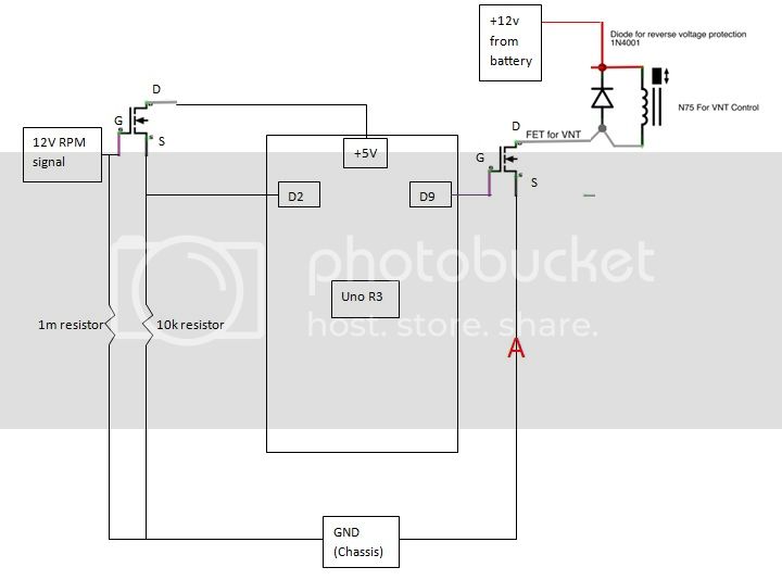
I am using an arduino uno r3 to try to control a variable geometry turbo charger using a vacuum operated actuator from a VW (N75 boost valve). This is controlled by the D9 pin through a FET.
Inputs to the board are throttle position sensor (TPS), manifold air pressure (MAP) sensor and engine speed (RPM signal). TPS and MAP sensor info is simple 0-5v input however RPM information is apparently in a square wave.
All the inputs work with the code I am using and show up the correct values when the arduino is connected to my laptop using hyper terminal. HOWEVR as soon as I connect the N75 the RPM reading goes crazy. Just to clarify, with everything connected everything works and reads properly apart from the RPM signal but if I disconnect the N75 the RPM signal reads perfectly again.
I have tried a diode between the source pin of the N75 FET and chassis (position A on diagram) and that allowed RPM to be read up to 2000 but after that it goes crazy as before.
As you can probably tell, I am a complete novice but Im sure there is a simple soltion to stop the N75 interfering with the RPM signal.
I have been told to try a capacitor in place of the diode (position A) but I was wondering if anyone could help me out with what value to use or if there are any other solutions?
Thanks for taking the time to read this, I hope it makes some sense
Thanks for the advice however I am struggling to work out how and where it would fit into my circuit. If someone would be willing to sketch it in I would be really grateful, many thanks.
Another small bit of advice - particularly in a noisy environment, it makes a lot of sense to put capacitors across your rails, or from ground to the various voltage lines. Values around 10-30 microfarads (uF) are good, perhaps you want a bit higher (up to 100 uF, I'd guess) in a noisy environment with spark plugs firing and alternator brushes connecting and disconnecting. Electrolytics are commonly used for these applications. Make sure you hook the minus end to ground and plus end to high voltage. This may or may not solve your problem, but is generally a good idea to keep the rails stable, and almost certainly can't hurt unless you put on something like a 100 milliFarads or more, in which case it might actually cause your car to start or run funny when it's in.
I think Martin is exactly right, Preconditioning (filtering and CLAMPING the 12V line can't cause anything to "not work" So at least a 100uHy Choke a .001 to a .01 Farad Cap (on the cold side of the choke) and a Tranzorb at a minimum... might well clean up what is a potential "noise receiver" and turn it into a workable ignition control or sensor network. You have a source follower for the RPM data input... try a 1nF cap to ground from the source. All of the noise "Power" in a square wave is contained in the leading edge... If you slightly slow the rise time you eliminate most of it's noise producing potential because most of the high frequency information (noise) is in the leading edge.
Thanks very much for all the help fellas, I have found a supplier of all the bits you suggest locally so I will give it a try tomorrow and let you know how I get on.
Docedison, just a couple of questions:
When you say to filter the 12V line, which one do you mean? The 12V line to the N75 from the battery or the 12V RPM signal line. I assume you mean the line from battery to N75 but best to check.
Also, excuse my ignorance but google isnt helping me out with which side of the choke is the cold side?
Thanks again for taking the time to help me out with this, I'm so close to having everything working once these little problem is sorted.
zsphil:
Thanks for the advice however I am struggling to work out how and where it would fit into my circuit. If someone would be willing to sketch it in I would be really grateful, many thanks.
The biggest issue I see is the 12v RPM signal. If that's coming off of coil-, be aware that coil- can have spikes as high as 400v. An opto-isolator there is crucial
I intended you to filter the 12V supply well and clamp it so that noise wouldn't be as severe as without the suggestions. and as I mentioned place a small capacitor "You have a source follower for the RPM data input... try a 1nF cap to ground from the source" (missing "across the 10K source resistor"). I did now (Finally) see a major mistake. In any control sutuation the grounding method should follow a star topology, that is all grounds must radiate or start at one common point and I don't see that done on your drawing nor do I see where the Arduino ground is connected... to anything. I am led to believe it must be the power connector on the board because you just don't show it. You don't show how the Arduino is powered at all and this point might well be central to the whole issue
Any spikes present on the gate of the Mosfet Must be transferred to the source circuit. Even though the Drain is tied to +5V it won't be dumped into the 5V source (the only place it can go except the input to the Arduino). A .1uF cap right at the drain lead, physically close to the drain. The issue comes back to the original design of the Arduino, It was meant to be a teaching device... Not a general purpose "Brick" for any control operation required... So when attempting to use it as a brick the user must be knowledgeable enough about the environment it is used in so as to be able to compensate or correct the "interface" between the Arduino and it's working environment. An Opto isolator is a solution. replace the 10K resistor with a 1K resistor and the opto... connect the transistor (collector) side of it from Vcc to a 10 K resistor and then to the Arduino input. You will have the same circuit as before. Presently when the gate of the 'fet is high so is it's source and thus the led in the opto will be on turning on the 5V source to the Arduino input. The other thing I don't see is any kind of a circuit that indicated any planning or fore-knowledge of an automobile's operating environment. Your drawing is more a statement of present conditions than it is a guide to a well thought out plan of action (Lack of power source for the Arduino, lack of any conditioning of the 12V source connected to the elements controlled by the Arduino. Primary side Sloane Kettering ignitions (Points and coil not electronic) versions can and DO have spikes many thousands of volts in intensity. There are Electronic ignitions that place 200 to 600V on the coil primary (Capacitor Discharge types). The Electronic ignitions use a magnetic sensor that produces a pulse that drives the controller to fire the spark plugs. That pullse can be upwards of 100V. Remember the points are now 4 6 or 8 "Lobes" on a shaft... causes a change in the magnetic path when each "lobe" is adjacent the sensor coil. I've never seen a distributor that had TTL level outputs for engine RPM.
Since I don't see any formalization of plan and scope of this project I can only think you are creating it as you go along.
Good engineering Starts with an accurate plan... The instructions for building the device and when you deviate from the plan then you are working without planning exactly what you wish to achieve.There is an old design maxim... "Plan your Work, then Work your plan". IMO