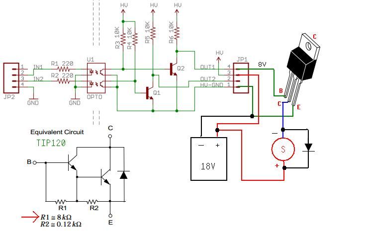
I have been programming for many years now, but I am just getting my feet wet on microcontrollers. I am attempting to control a larger current to power a solenoid valve that requires approx 16vdc. I am using an optoisolator breakout from sparkfun (BOB-09118) to protect the Arduino from the noisy system. Note that I am currently using a small hobby motor to test the circuit until I get it right, at which time I will use it to power the solenoid valve. My problem now is as follows... I am now using two 9v batteries connected serially to produce the approx 16vdc. The OUT1 pin from the optoisolator switches between a low current of approx 3v to a high of 6v when activated. I can use a 10k resister between the OUT1 pin of the optoisolator and the base of the TIP120. At first and this is sufficient. However, the current drawn by the motor really heats up the TIP120 quickly at which time i have to add more resistance between the optoisolator and TIP120 otherwise the motor just runs continually. If I start out with as much resistance as i require when the TIP120 is hot, there is not enough current to activate the TIP120. I attached a schematic as a visual aide. Any idea what I am doing wrong?