I'm struggling to understand where I'm going wrong with a very simple circuit.
I have light sensitive resistor that is being used to switch on an LED when the light level drops below a fixed value. I'm monitoring the analogue value returned by the sensor and the value being used to set the LED via the serial window. The values are as expected so I think the error is in the very simple LED circuit.
int sensePin = 0;
int sensorValue = 0;
int ledPin = 9;


void setup(){
  analogReference(DEFAULT);

  pinMode(ledPin, OUTPUT);

  Serial.begin(9600);
}


void loop(){

  int val = analogRead(sensePin);

  Serial.println(val);

  boolean ledVal = LOW;

  if (val < 750)
  {
    ledVal = HIGH;
  }
  else
  {
    ledVal = LOW;
  }

  digitalWrite(ledPin,ledVal);

  Serial.println(ledVal);

  delay(500);

}
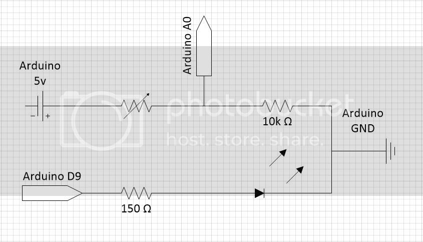
The attached jpg contains a circuit diagram that hopefully is a close enough representation for my error to be identified.
The LED is being switched on and off as the light levels change but the wrong way around; it is on when the ledVal is LOW and off when the ledVal is HIGH.
Any suggestions as to where I am going wrong would be appreciated.
According to your diagram, you have the LED between the Arduino digital pin 9 and 5v?
So then when the pin is high, which is 5v, there will be no PD across the LED and it will be off although you expect it to go on. Then when the pin is low, the LED is across 5v to ground and be on, when you think it will be off.
Correct wiring is to put the LED and its series resistor between pin 9 and ground. Then when the pin is high, there will be pd across the led and it's on; when the pin is low, the LED is at 0v both sides and will be off.
Edit.... as shown here although it shows the LED on pin 13
I actually had the LED and it's resistor between the 5v and GND with Arduino Digital Pin 9 also in the same circuit which I take to be wrong.
I've modified my circuit as you suggested and illustrated by the link in the edit, but unfortunately the LED is still behaving in the same manner as before, with it coming on when I'm setting Pin 9 LOW and off when I set Pin 9 HIGH.
Another other suggestions as to where I'm going wrong?
IanDG:
I've modified my circuit as you suggested and illustrated by the link in the edit, but unfortunately the LED is still behaving in the same manner as before
Post your new circuit? The previous version was wrong because the Arduino would be trying to ground the LED without any current limiting resistor when the output was LOW. This could easily damage the LED and/or Arduino output pin.
I should point out that I am as uncertain of the conventions used in circuit illustrations as I am of circuits themselves; hopefully it is sufficient to convey what I have on the board.
I'm struggling to understand where I'm going wrong with a very simple circuit.
I have light sensitive resistor that is being used to switch on an LED when the light level drops below a fixed value. I'm monitoring the analogue value returned by the sensor and the value being used to set the LED via the serial window. The values are as expected so I think the error is in the very simple LED circuit.
The LED is being switched on and off as the light levels change but the wrong way around; it is on when the ledVal is LOW and off when the ledVal is HIGH.
From what I can tell, val will be great when there is much light, and val will be small when there is little light. Therefore, the code above will cause the led to light when the ambient light is low. Is that what it's doing? If you want the opposite, code
You are quite right in saying the ledVal should be HIGH when the light levels are low and vice versa. The Serial.println(ledVal) is confirming that this is the case; it is writing out 0 when the values are over 750 and 1 when under 750.
However the LED is being illuminated when the light levels are high even though the value of ledVal is LOW. This is the opposite of how I intended the circuit to work. I know I could just fudge the values in the code but the point was to learn what I was doing and I am clearly getting something wrong.
If that is all the case then it may be that your circuit is not actually as you last posted?
If you remove the resistor lead from D9 and apply +5 to that lead, does the LED light?
If not, if you apply GND to that lead, does it light?
You know that the LED must be put in the right way and not backwards, right?
Following your directions I've found where I was going wrong. I have what seems to be an unusual breadboard and I hadn't realised one or two of the subtleties of the power and ground connections.
Having made sense of the board the circuit is now behaving as intended.
Thanks to everyone for the encouragement and help.
Sorry I'm not sure where I got it from. It was purchased as part of a previous attempt to get to grips with electronics - which obviously failed dismally. The ability to program the Arduino has convinced me to have another go so I got all the bits and pieces I had previously purchased out, one of which was the board, and added the UNO 3.
The board has no manufactures name on it or instruction with it. I had simply miss-interpreted the markings indicating how the various pin holes are linked. As soon as I simplified the circuit driving the LED I realised that one of the rails runs across the board despite the graphics that I read as meaning it only ran half way across the board.
It's just a bit embarrassing how long it has taken me to realise how it is wired up; it may be why I had so many problems in my previous attempt at electronics.
No. Based on the board illustrated in the link you included, instead of 2 of banks marked with blue lines there are 4 separated by 3 divisions.
The confusing bit is that the equivalent banks of 2 lines of holes to those marked with red and black in the illustration run along the ends of the 4 banks not down the sides. While each of the outer rows of holes runs across all 4 banks the inner rows of holes are broken in the middle so each side only crosses 2 the 4 banks. It was these that were the cause of my confusion.
Additionally there are 5 terminal connectors at one end and an additional bank of holes at the other end whose connections are oriented at right angles to those of the 4 main banks.
Having realised how the connections are configured I have been able to re-interpret the graphics and alpha-numeric markings to make sense of them.