Thanks for a great reply SirNickity, I'll try to be a little more specific when explaining.
If you're programming via serial, and the DTR (or whatever) pin is constantly low, and that is connected to the RST pin of your ATmega, it shouldn't work. Ever. TQFP or DIP, doesn't matter. You're holding RST low, which should keep the chip in a coma. The 0.1uf series cap is absolutely necessary to turn that constant DC low into a low pulse.
I can see that it wouldn't work if the RST pin was constantly LOW, but I have a 10k pull-up that forces it HIGH. The programmer (my arduino) or a simple button will force it LOW thus resetting it or making it capable of being programmed, won't it? But as I said, I've made due without a cap in every other design (perhaps 20 different designs) without any problems with the uploading.
OK, that's how you physically broke out the pins, but you didn't explain the process you used to get the bootloader onto the TQFP. DIP adapter in a breadboard with its own crystal, caps, and reset resistor -- ICSP to Arduino running Arduino-as-ISP sketch? (This is what I'm assuming based on your description, but you're leaving out some detail.)
You assumption is right ![]() Breadboard, 16Mhz crystal, 10k pull-up, caps and then jumper wires from the breadboard to the arduino board. I then removed the DIP atmega from my arduino (the one with the ISP scetch on it), rewired the jumper cables so that they went from RX and TX instead and then uploaded the blink example (with AVR ISP), that went fine and I later tested with my DMM that the code was working correctly. I'm not sure what else to tell
Breadboard, 16Mhz crystal, 10k pull-up, caps and then jumper wires from the breadboard to the arduino board. I then removed the DIP atmega from my arduino (the one with the ISP scetch on it), rewired the jumper cables so that they went from RX and TX instead and then uploaded the blink example (with AVR ISP), that went fine and I later tested with my DMM that the code was working correctly. I'm not sure what else to tell ![]()
Sounds like we need to start over. Can you explain exactly how you have everything wired? Photos help. Also, if your PCB is involved in this, the schematic and an image of the board layout will help as well. I'm taking from your description that you do not have an electrolytic cap anywhere? You should. The 470nF (odd value BTW, but OK...) ceramic decoupling cap will shunt noise, but it doesn't do much for bulk storage. That is likely to cause power starvation, which is precisely what you don't want for stable operation.
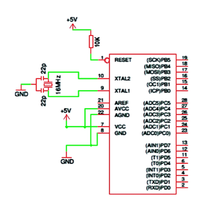
Add a 470nF ceramic cap across the rails to this schematic and you have it: http://www.open-electronics.org/wp-content/uploads/2012/03/Arduino_standalone_minimal.jpg
Here's the board layout: http://i42.tinypic.com/2qakbdg.png
The blue wires are jumper wires, not actual traces. You can see the pads right nest to RST, RX and TX that I soldered the wires going to the arduino to. The power SMD package you can see on the left is a regulator, it is not present and Vin and Vout are simply shorted together. The 470nF decoupling cap is C2 and I actually see now that it's kind of close-ish to the GND pin of the MCU, but not that close to the +V pin ![]() I have been looking at C3 (the crystal cap) and thinking it was the 470nF cap
I have been looking at C3 (the crystal cap) and thinking it was the 470nF cap ![]() Anyway, the 10k RST pull-up is R1 and +V and GND is connected to SV2 in the upper right (R11 is a 0Ohm jumper resistor).
Anyway, the 10k RST pull-up is R1 and +V and GND is connected to SV2 in the upper right (R11 is a 0Ohm jumper resistor).
You have a scope? Good. Do you also have a logic analyzer? Are you saying all three -- Reset, TX and RX -- were HIGH at all times? Yeah, that would certainly make it not work. There's absolutely a bad part or wiring error(s) there.
I don't have a logic analyzer. I don't see anything when scoping, but that might just be because things are happening very fast. I don't know how the actual uploading is happening, but I can assume that it's some communication back and forth? If the programmer isn't receiving an acknowledge after the first package, it might just sit there waiting? I've assumed that this first package is transferred too fast for me to pick it up on the scope