DCF77 Master Pulse Bracket Clock

This is my first Arduino Project so I am sure you will find plenty of ways to improve on my code.

I wanted to build a clock as a backup to my old logic controlled Master Clock http://home.btconnect.com/brettoliver1/masterclock.htm this clock had a DCF77 decoder using logic gates that was just used to keep the clock in sync every minute.

I wanted a true DCF77 decoder that would set the time and provide pulse outputs to drive all my different types of slave clocks.

I came across Arduino and in particular the Time, DCF77 and Timezone libraries. All the hard work was done for me. I found a cheap 20x4 LCD display on ebay http://www.ebay.co.uk/itm/161107072069?ssPageName=STRK:MEWNX:IT&_trksid=p3984.m1439.l2649 that only required 2 wires plus power and I was away.

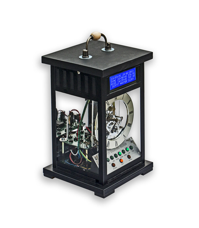
I built the circuit out on breadboard to test it and then fitted into a "hacked" Ikea lanten. To keep the size down I fitted the Arduino chip on to the vero board with the other components.

I added an old skeleton clock movement to show the time and used an LED panel to monitor the clock pulses. I cut out the old quartz driver from this clock then connected my "quartz motor" drive pulse from the Arduino to it.

The skeletal movement caused some problems as I found when the clock synchronised (about 6 times a day) the LCD display would jump a second to show the corrected time but of course the clock motor would not. I had to add a bit of code to make the quartz cock motor double pulse when the clock corrected. I have also done the same for a few of the clock pulses.

I have also added a battery to keep the clock running if I need to "carry time" around the house to check my slave clocks are in sync.

My master and voltmeter slave clock chime the hours in sync so I have added a quarter chime to this clock. On the hour the quarter chime goes off 3 seconds early so the chime stops just in time for the hour chimes on the other clocks to start.

The chime is a sample and is played back via an ISD1730 chip.

The LCD display shows time and date, time last synchronized, synchronization status, time of last missed pulse and number of missed pulses per day.

Here is a link to a very short video animation I made showing the clock from 23:59:55 seconds to 00:00:32 and gives an idea of the clock working including the chimes. The hour chimes are from my other clock and the clunk every 30 seconds are from my 30 second slaves.
You Tube Video Link

Here is my code. Bear in mind it is my first attempt at writing for Arduino!
I have based lots of the code on the example files provided with the libraries.
The timezone is set for London England.

Link to download latest code http://home.btconnect.com/brettoliver1/LCD_Master_Clock/DCF77_LCD_Clock.zip

Thanks for sharing. I really love the look you've arrived at here.

Here is the schematic.

and vero layout

Thanks strykeroz.
I think I spent more time modifying the case than building the clock.

oliverb:
I think I spent more time modifying the case than building the clock.

I think it was entirely worth it!

After reading a little to work out what you've done here, it transpires we have no LF time transmitter in Australia however there are infrequent reports of the Japanese time signal being received weakly. That's a shame. It's not that I need another project for the queue...but this does look cool, and my dad is a retired clockmaker so thought I had a likely source for the naked movement in his shed 8)

Geoff

it transpires we have no LF time transmitter in Australia

What about using a GPS module instead?
I think it will be my next project.

Nice!

I removed the old Red SMD LED off the I2C interface from the 4x20 LCD display and added a bright Blue LED on a short length of wire in it's place and used it to illuminate the inside of the case. I have also removed the rear piece of glass and added a mirror.

I managed to get this picture this morning showing the clock in a dark room.

oliverb:
I managed to get this picture this morning showing the clock in a dark room.

Pretty... but... you can't actually see the time! Doesn't that defeat the point?

Ideally you should have some LEDs on the clock hands but that would be difficult to wire (you'd need some sort of DC brushes).

Maybe some fluorescent paint and UV LEDs? A different color for each hand?

I know what you mean but of all clocks skeletal clocks will always be more difficult to read.
In real life the hands are much clearer as our eyes can see a far wider range of light and dark than my digital camera.

I have had to manipulate the dark picture in photoshop just to get it a bit closer to real life. The blue LCD display for example just came out all white. I had to take 3 pictures all at different exposures then stitch them together to get an even exposure.

Here are a couple more pics from different angles showing the 2 boards and wiring etc.

Congrats on the Hack-a-Day mention !

Geoff

oliverb:

it transpires we have no LF time transmitter in Australia

What about using a GPS module instead?
I think it will be my next project.

How about both, so you can compare the results... :slight_smile:

strykeroz:
Congrats on the Hack-a-Day mention !

Geoff

Thanks Geoff I did'nt realize it had been posted so quickly!

There have been some good comments so far but I know from before some of the members don't hold back if they don't like something. :slight_smile:

fungus:

oliverb:

it transpires we have no LF time transmitter in Australia

What about using a GPS module instead?
I think it will be my next project.

How about both, so you can compare the results... :slight_smile:

I think in the long run they are both 100% . I don't know about GPS but DCF77 only updates once a minute on a perfect signal for the other time your are relying on the Arduino for timing. My clock looses a second around 6 or 7 times a day (it always corrects itself) so I presume using the Arduino for a clock without any external correction is not a good idea.

My voltmeter clock http://home.btconnect.com/brettoliver1/Voltmeter_Clock/Voltmeter_Clock.htm built from a design by Alan-Parekh Multimeter Clock – Simpson 260 - Alan Parekh's Electronic Projects losed many seconds a day until I sync'd it to my original logic master clock every 30 seconds.

I would expect 1 second in 2 weeks on a properly adjusted quartz clock in a reasonably stable temperature. Maybe I could add a trimmer to the Arduino crystal ?

oliverb:
I think in the long run they are both 100% . I don't know about GPS but DCF77 only updates once a minute on a perfect signal for the other time your are relying on the Arduino for timing.

Yes, I looked into the DCF77 signal a few months ago because I had an antenna from a broken clock. I decided not to use it because the signal is terrible in this room (I live in a tall building). The signal was almost 100% noise. It was OK out in the street but not in here.

(It's fun to look at the DCF signal on an oscilloscope - you can see the pulses very easily out in the street...indoors it was just garbage, no clear pulses at all)

oliverb:
My clock looses a second around 6 or 7 times a day (it always corrects itself) so I presume using the Arduino for a clock without any external correction is not a good idea.

It would be terrible. If you put two Arduinos running "blink" side by side and simultaneously press reset on both they only take a minute or two to noticeably go out of sync with each other.

oliverb:
I would expect 1 second in 2 weeks on a properly adjusted quartz clock in a reasonably stable temperature. Maybe I could add a trimmer to the Arduino crystal ?

Maybe better to figure out the time error in software (you have a good reference clock!) and add extra cycles to the calculations to compensate.

I think it's the crystal that is the problem quartz clocks use a 32.768Khz crystal. You just divide by 2 15 times to get 1 second. 16mhz on the Arduino divided by 2 24 times gives 0.95 of a second. Maybe there are other value crystals that will work?

oliverb:
I think it's the crystal that is the problem quartz clocks use a 32.768Khz crystal. You just divide by 2 15 times to get 1 second. 16mhz on the Arduino divided by 2 24 times gives 0.95 of a second. Maybe there are other value crystals that will work?

I think an AVR chip can divide by 16 million ... it won't rely on a simple counter overflow to indicate seconds.

I notice there are loads of Real Time Clocks for Arduino they all seem to have crystals of 32.768kHz. Is this what they do just keep the time in sync?