Current Amplifiers

Hi all,

I've been searching the internet and textbooks for information about current amplifiers. Id like to use one to amplify a small signal.

Is a current amplifier readily available in some sort of an op amp chip or is it something i need manually do with like 2 bipolar transistors. (1 NPN and 1 PNP)

To be honest I'm a bit confused about them as there are so many sources saying different information about them.

If someone could possibly enlighten me about them, I'd be most grateful.

Hi, can you explain your application, and what you want to do with the current measurement once you have got it?
What level of current is it, A, mA, is it AC or DC?

Thanks Tom..... :slight_smile:

If i say too much ill be accused of "Cross posting" because I've already mentioned my application.

But essentially its a signal from a photodiode - looking at the spec sheet theres a graph which correlates short circuit current to lux

Essentially 10^5 lux is equivalent to 1 mA.

Im getting way less than that from my photodiode but i can't really tell with a standard multimeter - i think its in like micro amps range.

i just want to amplify that and then maybe after that, convert it back into a voltage.

I want to amplify the current as the spec sheet shows a linear relationship and as far as I'm aware, measuring voltage will give a logarithmic result.

But essentially its a signal from a photodiode - looking at the spec sheet theres a graph which correlates short circuit current to lux

Essentially 10^5 lux is equivalent to 1 mA.

In that case, you don't need a "current amplifier". There is a well-known relationship between voltage, current, and resistance called [u]Ohm's Law[/u]. :wink:

Connect the photodiode to a known resistance (probably a high resistance) and connect to a regular 'ol op-amp voltage-amplifier (if needed).

The op-amp can be used to boost the current and/or the voltage, but the output-voltage will be proportional to the input-voltage, with the actual output current depending on that voltage and the load impedance/resistance.

...I don't think I've ever seen a "current amplifier". I have seen schematics for a "transconductance amplifier", which converts a voltage to a proportional-amplified current, but I've actually never seen one in use.

No, i definitely need a current amplifier. The amount of light I'm getting in lux is from 10^2 to 10^4

so from say the order of 100 to 10000

so thats between micro amps and like 0.01 mA.

You see the problem is that at a certain level of light , the photodiode saturates out - at 450mV. But the readings go above that.

I get a linear relationship with doing current which is very useful for me.

this is why I tell you (in the other post) that a log amplifier is required for photodiode (to compress the range) current amplification. because the light can vary with a big ratio.
or you must select a scale with a resistor + switch in the feedback of the operational amplifier.

Hi, the photodiode is to be regarded as a current source.
You would need to look up current sense amplifier or a transconductance amplifier.

I don't know if these will help, optical detection using photodiodes is not my field.

http://www.ti.com/lit/an/sboa035/sboa035.pdf

The ti link looks very informative, and how to use an instrument amp to convert the output.

Hope it helps, Tom........ :slight_smile:

yes I've given these links in his other post.

If i say too much ill be accused of "Cross posting" because I've already mentioned my application.

It matters little if you say too much.
It is cross posting and you are getting the same answers you got in your first post.

This is like a child asking mom a question and not liking the answer, asks dad. However in science the same question always has the same answer and you don't seem to be listening.

More like sitting on the sofa and asking mom a question, then moving to a chair and asking mom the same question again.

Let me try to help him from a noob perspective... :grinning:

MrDropsy you shouldn't try to amplify the current, you don't need to. Ohm's law states that current, resistance and voltage are linearly correlated, which means you can linearly convert current into voltage. This same principle is used to measure an unknown current flowing through a circuit through what is called a shunt resistor.

Now, if you put aside your initial idea to amplify the current, what you have left is voltage.

Step 1. measure the current produced by your photo-diode by converting it into voltage
Step 2. use an op amp to amplify the voltage so that it fits into the range you need

If you accept Ohm's law and its linearity, whatever happens to your current then it is linearly reflected onto your voltage. If you needed to do something on the current (apply a logarithmic scaling as an example), you can do it on your voltage and obtain the exact same result (well, within some limits, not because ohm's law is not correct, but because real world is not perfect :wink: ).

Does this help? :cold_sweat:

Yes thank you rlogiacco,

This means i need to use a transimpedance amplifier. Ive sent you a private message. But Im trying to design the values for the feedback resistor and capacitor.

There are many formulas and many things to consider which makes it difficult. im testing a circuit i put together and I am getting a lot of noise. Im using the BPW21R photodiode, a 50 ohm resistor and feedback capacitor of 0.1 micro Farad.

As far as im aware the feedback resistor dictates gain and i think i need a gain of around 50. I think a lot of the problem now is all the noise etc.

MrDropsy please avoid PM for questions, mostly because you'll get faster answers through normal forum posts than on PM as the potential audience is wider.

I'm a noob myself, so please validate everything I say either with somebody else on the forum or with other sources: don't take my words as those coming from an expert because I'm not.

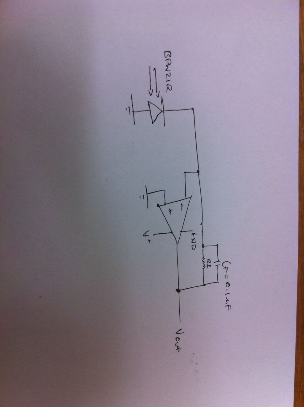
Now back to your questions and circuit: first of all please make a diagram of what you have so far so that we can talk of something more real than just thin air.

Second, the amplifier gain, assuming we are talking of an inverting amplifier configuration, is determined by the ratio of two resistors: the one on the feedback connection (from the opamp output back into the negative input) and the one on the negative input.

I believe a little bit of basic knowledge about opamps would help you here, so these are the two rules about an ideal op amp (real op amps do their best to match the ideal op amp)

  1. no current flows out of an opamp
  2. the op amp output will do it's best to make it's inputs to be equal in voltage

When selecting an opamp you have a lot of considerations to do, one being the supply voltage.

Every op amp will need some voltage supply in order to drive the output. When an opamp is classified as "single supply" that means it can usually be powered by 5V. When such characteristic is missing from the opamp description it means we are talking of "dual supply" opamps, which require 12-15V. Usually, when talking about Arduino, you want to stay within the 5V range, so pick a single supply one.

Another opamp characteristic is its capability to have the output going close to it's supply (speaking of voltage here). So assuming we are talking about a single supply opamp (5V) we talk about a rail-to-rail opamp when the opamp output is capable to go very close to the supply voltage. usually it's easier it goes very close to the positive voltage and a little less close to the negative voltage (or ground).

So, I assume you need an opamp that swings it's output between 0V and 5V while being supplied 0V and 5V: this is a single supply rail-to-rail opamp, like the MCP60x opamp family somebody else was suggesting (http://ww1.microchip.com/downloads/en/DeviceDoc/21314g.pdf).

Now, please, draw a schematic of your circuit naming your components and providing values so we can discuss the specifics.

I understand basic op amp ideal characteristics. Im also aware that that arduino is 0 to 5V. Although currently im working with out the arduino just so I can see something happening. So im putting in +-10 V just so i can see something happening - ive tried to vary the amount of voltage as well.

But for the sake of this lets just assume its 0 to 5 V

Attached is the circuit im finding all over the internet and the one im trying to implement. You mentioned that the gain is controlled by 2 resistors. I understand that the gain is controlled by the ratio between the two resistors Vo/Vi = - R2/R1. However the circuits im finding for the transimpedance amplifier always just have the one resistor for gain control and one capacitor in an attempt to control noise.

Currently im using the LM324N - i think its a pretty general purpose.

I hope to end up using the TL072 as it has low noise and JFET input.

I forgot to write the value of the Rf - in my circuit currently, its at 100 ohms

Here are some images from my oscilloscope. I changed resistor value to 1 M ohm and capacitor to 1 nano farad.

The circuit is responding to light and lack of light but not in the way expected.

photo 1 shows ambient light

Photo 2 shows when i put my finger over the photodiode

and photo 3 is when i shine an intense light on it - i think the oscillations increase when i do this also.

photo 1.JPG

photo 2.JPG

photo 3.JPG

Figured if i ground op amp inputs, id reduce noise. I also put capacitors across the rails to ground. This significantly reduces me noise.

That and using a 12 V battery rather than a power supply.

the oscillation you see in pic 1 is the sinewave from your AC bulb :wink:
1/0.020 = 50Hz
the oscillation on the pic 2 is a capacitive coupling of the sensitive input and high gain amplier with your finger. Your body create a big antenna
as explained in other topic 1M is a very high gain!

To give you an idea my laser harp sensor "see" scattered laser light at 3 meters with only 220K of feedback in my I/V converter!

the LM324 in not rail to rail input/output and even if they said "low voltage" it's for biased input not from groud to V+

it's for AC signal with V+/2 bias at the input and the output will move around the Vsupply/2. this is why we must use AC coupling capacitors in that case.
for your application you must use a rail to rail in/out amplifier or +8v/-2v supply voltage to get à +5V swing voltage at the output.

look this circuit:

R3 and R4 makes a voltage divider to VCC/2 for the V+ input. it's a single voltage application. and you have AC coupling capacitors (C1 and C2) at the input and output to remove the DC bias voltage

from LM324 datasheet:
Large Output Voltage Swing 0V to V+ − 1.5V
so you can get the ground but only 3.5V max with +5v supply. over this value the signal is deformed

Thank you genesis92 for your input. First im just experimenting to see if it response to light at all. I have reached where it clearly does respond to light.

The difference between dark and very bright gives me a voltage swing but only time will tell whether that swing is large enough.

The problem with arduino is that its only 0-5V - surely that limits the range i possibly achieve.

Do you know if i put in a negative voltage through the arduino?

i am aware there are voltage converters - so i can put in +5 and obtain -5. So that way i can have -5 to +5.

Im not sure if this is a wise thing to do.

Do you know if i put in a negative voltage through the arduino?

No, that will damage the Arduino.

Im putting through the signal from my circuit into arduino. But only using 0 to 5V gives me a range of around 0-700,

How can i maximise the full range 0-1024 when i cant even get more 5v for the board