please help me with the concept, i explain after the situation introduction
i have been recently looking into arduino control of electrical outlets. unfortunately the popular relay boards all use a relay that uses a constant power in the coil to activate the switch. it seems even sellers on ebay are uninformed and selling some of these as latching switches.
i was looking into reed relays and saw that the BESTAR ELECTRIC LTD. BR-1050 only can run 10W total, so it isn't suitable for mains power of at least 200W.
Mercury switches and Mercury wetted relays seem to be the correct pieces of reliable equipment, especially for durability.
as far as mercury wetted relays go, i have only seen the hgrm-55211-p00 which only can run 100W, 500V, 2A max.
also i am fuzzy/not totally comprehending about how to set up the circuit.
if you will please review my concept and advise me on what i may use/need/and need to know
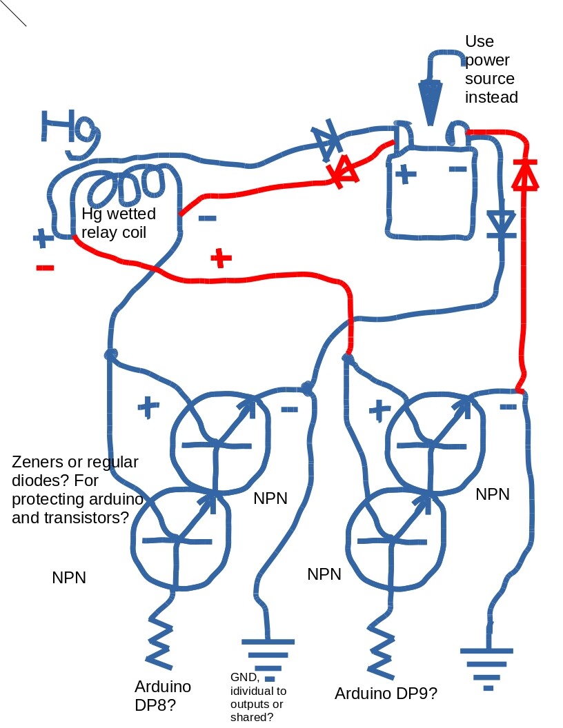
i figured from a video called "Using NPN Biploar Transistors with Arduino, PIC " by Lewis Loflin on youtube that it will need a darlington transistor configuration.
if i need to run a coil or something that may feed back high voltage when shut off, it will seemingly need diodes to protect the transistors and arduino pin which can handle only 20mA.
arduino grounds to negative and the exact setup of the transistor still confuses me as the base is P in NPN.
the other part to the concept is running two wires per terminal from a battery to power the coil in an on and a reversed off configuration. the positive would have a diode in and out on the two wires and the same for the negative.
I couldn't understand your drawing. I can only help the first part of your question. If you don't want to spend power holding a relay coil, you can get a latching relay. There are some latching relay boards for arduino from seeedstudio and jeelab etc. Just google arduino latching relay.
I also don't understand your drawing. When e.g. the left transistors are on, current flows from the power source through the left red diode to C, from E to the common (shared) GND and back to the power source through the right red diode - killing the transistors or diodes, and not affecting the relay coil.
In case you intended to use something like a bridge rectifier, this will work only with an alternating current source, but will not generate AC. Better think of a flip-flop, with the relay coil between the complementary outputs. Then the collector resistors must be chosen to provide enough current through the coil, and the transistors must support both the current through their collector resistors, as well as the current flowing through the coil. Once the relay has toggled, both transistors can be turned off, so that they have to support the high currents only while toggling.
In a more economic approach you replace the passive collector resistors by active (transistor) pullups. Such circuits are readily available as H bridges. These bridges are designed to support high voltages and currents through DC motors, so that they also are suitable to drive relay coils requiring high operating power. Like H bridges allow to turn DC motors left or right, they can generate current through a relay coil in both directions. Once the relay has toggled, the bridge can be deactivated to reduce power consumption.
Or you get a latching relay module that can be steered directly from Arduino output pins. Eventually let this relay drive another relay, that supports more current or higher voltage, depending on your needs (200W load).
i am still unsure about how to work out the darlington configuration, maybe with three
i copied from here
at 20:25 the instructor switches from a modified darlington to a regular darlington.
the part i took note of for theory was the immediate picture at about 14:00 to 15:00,
where he talks about hfe or Beta being to high to run a motor on the arduino
and switches to a modified Darlington circuit to show how to keep the Arduino safe.
the video i watched gave me data. i came up with a general idea for how to use the concepts shown in it. i worked that concept out on drawing, leaving out specifics like types of parts, values and formula calculations i still don't know. i also don't know where to find the right Hg wetted reed relay yet.
i am unsure where to put diodes to prevent from high voltage surges from the coil so i revised the drawing only addressing what was told to me about the drawing, waiting for the next pointer So I Understand It, instead of scrapping it.
Why are you worried about the power usage of a relay that might be 1/1000 of the load it has to switch.
Why use poluting and dangerous heavy metals for things that might not need it.
Can't you just use a common relay board.
Leo..
teleporturtle:
please help me with the concept, I explain after the situation introduction
I have been recently looking into Arduino control of electrical outlets.
OK, the answer is - you use the relay boards that are readily available, consistent with the regulations in force in your country as to how you wire them into your system.
There is no need at all to use latching relays for this application. Just none.
The amount of power the standard relays draw to be switched on is quite negligible. Since you are controlling "mains" power, you use the mains power - through a power supply - to power the relay control circuitry. If the mains power goes off, it does not matter whether the relays are operating or not as there is no mains power for them to control.
And you do not need the latching function because if the mains goes off and then comes back on, your whole control system must re-initialise in order for order to be restored and you want the system to "fail safe" with all outputs switched off. If you need the system to "fail safe" in any other manner, then you must take quite different steps to achieve that.
So - latching relays unnecessary, mercury wetted relays (which are only needed for high speed switching) unnecessary.
What you probably need to do, is to explain better what you really want this system to achieve. Thus, the XY problem".
You need to learn a lot about electrical circuits before you bother about latching relays or mercury wetted relays. You will have sufficient difficulty wiring up the available relay boards.
"If you don't mind using a transistor for switching higher current you can get very similar relays with contacts rated up to 16A."
can you let me know more about this?
i have some power transistors but i think you mean something else.
i also am very interested in learning to build with the mercury wetted reed relays
Wawa says "the power usage of a relay that might be 1/1000 of the load it has to switch." i don't know what he means. does he mean a mercury wetted reed relay can switch 1000*200W= 200,000W, awesome because that is awesome. i don't think he is though. what does he mean.
Paul__B says "mercury wetted relays (which are only needed for high speed switching) " so i could switch it on and of by the picoseconds?
John, what do you think of my revision "schematic edit.jpg" did i fix part of the problem? please let me know more about the transistor switching better relays.
teleporturtle:
i also am very interested in learning to build with the mercury wetted reed relays
I can't really imagine why. They are an obsolete technology (which is to say, there should be a couple in my shed - somewhere), possibly used for particular reasons in a few military applications.
my mistake, only "The current rise time through the contacts is generally considered to be a few picoseconds"
", however in a practical circuit it will be limited by the inductance of the contacts and wiring. It was quite common, before the restrictions on the use of mercury, to use a mercury-wetted relay in the laboratory as a convenient means of generating fast rise time pulses, however although the rise time may be picoseconds, the exact timing of the event is, like all other types of relay, subject to considerable jitter, possibly milliseconds, due to mechanical imperfections.
The same coalescence process causes another effect, which is a nuisance in some applications. The contact resistance is not stable immediately after contact closure, and drifts, mostly downwards, for several seconds after closure, the change perhaps being 0.5 ohm."
teleporturtle:
Wawa says "the power usage of a relay that might be 1/1000 of the load it has to switch." i don't know what he means.
A normal relay, as used on common relay boards, uses ~350mW. 1/3watt.
A fraction of e.g. a 500watt appliance that you might want to switch.
If you would power a relay like that for a crazy 12 hours a day, it would use 1.5Kw/year. ~$0.30
You must have special reasons wanting to use a more expensive and poluting technology.
Why are you worried about lifetime.
Ar you going to send a probe to some distant galaxy.
Why not tell us what you have in mind.
Leo..
anyway, i read up on relays a bit and i am hard pressed to find the sources and what i read exactly about them.
what i got from it is the coil does give off interference, maybe not a big deal.
the contacts can have arc problems, buildup oxides/erosion and
i like to build things that last, longer than me maybe.
i don't remember where i read that using standard relays to power CFL lights are not favorable and like i said, i am hard pressed to find the data.
furthermore i am wondering about how to pulse LEDs on and off for efficiency and that is another thing to learn so this is straightforward about the wetted relay.
unfortunately, i don't know that i can use that for picosecond pulses although if i learn more i may at least see why.
i am hoping to learn about high efficiency switching power supplies; how to build them, that is another thing to learn.
pulsing high voltage equipment is something i don't know about yet as i am learning. like tesla type stuff.
right now it is simple, i am not comfortable with common relays and see promise in wetted relays.
they as quoted have laboratory capabilities, which i may finding myself needing.
i am here to build machines, one step and leap at a time, or many, depending on the difficulty.
teleporturtle:
right now it is simple, i am not comfortable with common relays and see promise in wetted relays.
Well, that is very nice and amusing, but away from the fantasy world, you were talking about switching mains power, so for that if you are serious about it and not just spinning your wheels here, you need some common mains rated relays or SSRs.
Probably those available on eBay will suit, or else if you want them fully certified, some DIN rail mount modules.
teleporturtle:
unfortunately, i don't know that i can use that for picosecond pulses although if i learn more i may at least see why.
How can you be sure that you might not need femtosecond pulses in future? It never hurts to be prepared. You'll really have a laugh at all the nay sayers.
aarg:
How can you be sure that you might not need femtosecond pulses in future? It never hurts to be prepared. You'll really have a laugh at all the nay sayers.