I'm looking for something that can convert 3v PWM from an RC receiver to DC with as response time that is as fast as possible. The output will just be going into another circuit and will be very low amp. The output needs to be above 5v though.
The best thing I've found so far is to use an arduino UNO with this:
Am I compromising response time with this board?
Does "...selectable output gain 1x or 2x" mean that I can get up to 10v if the arduino is supplying 5v?
David82:
I'm looking for something that can convert 3v PWM from an RC receiver to DC with as response time that is as fast as possible. The output will just be going into another circuit and will be very low amp. The output needs to be above 5v though.
To get an output above 5V, you'll need a power supply of the required voltage.
Does "...selectable output gain 1x or 2x" mean that I can get up to 10v if the arduino is supplying 5v?
A DAC doesn't take PWM input, either. It takes digital values and converts them to an analogue value. In the case of the one you linked, it can go as high as the supply voltage. ("rail-to-rail output")
If you already have PWM, all you need is a power supply of the required voltage, a MOSFET for switching, then a filter which smooths the PWM, creating a DC voltage.
You feed the lower voltage PWM to the gate of the MOSFET, which is connected to the supply of your choice via it's drain. This will provide a level-translation of the voltage. Then the filter to smooth.
And "very low amp" is a very loose term. It will determine the size of the power supply and the MOSFET used to switch it.
Perhaps some more info is in order. What do you need to drive/control with the output?
OldSteve:
If you already have PWM, all you need is a power supply of the required voltage, a MOSFET for switching, then a filter which smooths the PWM, creating a DC voltage.
I wanted to use the arduino to receive and interpret the PWM signal, and then the DAC to output 4.5v-7v. I'll be supplying 12v to the DAC. I need to do this for two different PWM channels.
The problem with the the circuit you describe is the filter that is used to smooth the PWM usually involves a large cap. That large cap also slows the response time a lot.
The arduino + 2-channel DAC should be fine IF and only if it "...selectable output gain 1x or 2x" means that I can get up to 10v if the arduino is supplying 5v
David82:
The arduino + 2-channel DAC should be fine IF and only if it "...selectable output gain 1x or 2x" means that I can get up to 10v if the arduino is supplying 5v
No. you can't. I said that. The DAC output can go rail-to-rail, and operates on 5V max, so it follows that it's output is limited to 5V.
If you want 10V analogue output, with a faster response than a filter cap can provide, then you'll need a DAC with a 10V supply.
And if you want 'amps', as you stated, then the DAC output won't suffice either.
I ask again, what do you need to drive with the output?
OldSteve:
No. you can't. I said that. The DAC output can go rail-to-rail, and operates on 5V max, so it follows that it's output is limited to 5V.
What does "...selectable output gain 1x or 2x" mean then in the product description? It sure seems to imply that you can double the output of the DAC if you want. If you can, and the input is 5v from the arduino, then I should get 10v max, or close to it. (I only need 7v max anyway)
The output of the DAC will just be going into an existing circuit. It is just reading the input like an arduino would. No need to care about any of that end of the project. The important part is only two questions I originally posted.
How about reading the manual (click ) of that board.
It isn't a single sheet piece of paper, but it isn't very impressive either.
It tells you, if you like to know more, to read the on board chips' datasheet (click once more), where it tells you on page one what this gain option means (right column, 2nd. line if you take a period as the end of a line, or 5th. if you are counting the lines you see.
I really don't know what more to tell you.
Specs of the RC receiver? Normally for this kind of modulation you measure the pulse
duration directly, not smooth it, since the duty cycle is undefined (RF signals drop out
occasionally).
Typically these days you use a DAC at the micrcontroller voltage and amplify it with an
opamp. You can also use high frequency PWM, boost that and smooth (smaller cap needed
at higher frequencies).
Does "...selectable output gain 1x or 2x" mean that I can get up to 10v if the arduino is supplying 5v?
Answer to 1 is yes: you will always end up with some delay, certainly when you decide to read a value by some processor, convert it, send it to an ADC to get an analogue signal out of it.
Answer to 2 is no, not without additional hardware.
Did you read the datasheet i linked to ?
If so, then i think you didn't understand all of it.
Here's a hint:
Datasheet:
Absolute Maximum Ratings †
VDD....................................................................... 6.5V
All inputs and outputs w.r.t ........................ VSS –0.3V to VDD+0.3V
The problem with the the circuit you describe is the filter that is used to smooth the PWM usually involves a large cap. That large cap also slows the response time a lot.
That means you want a better filter. An RC filter is only a first order filter. In order to get a steeper slope you need a much better filter, perhaps a sixth order one. You can make a 6th order filter with three op amps.
Something like this could convert 5volt PWM to 4.5-7voltDC.
<50msec settle time and <10mV p/p ripple at ~500hz PWM.
V1 is PWM in, V3 is 5volt, V2 is 7volt + opamp sat.
R5 = 4.5volt adjust. R4,R3 = 7volt adjust.
Leo..
You weren't taking any notice of my replies, were you? That's why I stopped replying here. I said "NO" twice, yet here you are still flogging that same dead horse!
David82:
Yep. So the answer to #1 is "generally no" since it uses a resistive string architecture. The Answer to #2 seems to be yes.
Question 1 makes no sense.
Question 2 the answer is no. Think about it, if you have an amplifier with a gain of 1000 and you put 1V on the input would you expect 1000V out? Maybe you would, if so then you do not understand very much. An amplifier can only supply as much voltage as it is powered with.
jackrae:
The 1X and 2X refers to the fact that you can have 1 channel or 2 channels of output (Output A and Output B)
As I understand the datasheet, the 1X or 2X refers to the gain, plus there are two output channels.
Dual channel output and selectable output gain 1x or 2x
But, David82, this still doesn't mean that the chip can output a voltage higher than it's supply, just that it can amplify low value signals by 2 if needed, within the constraints of the supply voltage, of course. Hence the datasheet's reference of "rail-to-rail" output. Not "2 x rail-to-rail".
Edit: MarkT appears to be on the right track. The PWM won't be PWM like an Arduino PWM output anyway.
MarkT:
Normally for this kind of modulation you measure the pulse duration directly, not smooth it, since the duty cycle is undefined
I have a remote controlled lawn mower that is built out of a 24v power chair and a 24 lawn mower. It works fine but I use servos to physically move the joystick that controls the power chair's wheels. I'm trying to simulate the existence of that joystick electronically, instead of physically moving it with servos.
The joystick takes in 6v and 12v DC. It outputs 4.5-7v flat DC for each of the two axis, back to the electronics housed in the control box.
So I'm getting a 3v PWM signal from the RC receiver and I'm looking for the most straightforward, off-the-shelf way to convert that PWM to that DC range. I've wasted tons of time already building an op-amp for it but couldn't get anything flatter than a .25v sawtooth wave, which also had way too much delay.
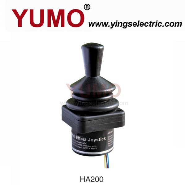
The joystick is a hall-effect joystick similar to this one:
Wawa:
Something like this could convert 5volt PWM to 4.5-7voltDC.
<50msec settle time and <10mV p/p ripple at ~500hz PWM.
V1 is PWM in, V3 is 5volt, V2 is 7volt + opamp sat.
R5 = 4.5volt adjust. R4,R3 = 7volt adjust.
Leo..
The PWM signal is 3v. Does that change the circuit much?
It outputs 4.5-7v flat DC for each of the two axis
So it's a dual-channel system? You'll need to do some reading on 2-channel RC systems. A simple 1-channel DAC will definitely not do what you want.
I know next to nothing about multi-channel RC systems, so can't help further I'm afraid, except to say that you'll need to learn how to decode the signal back to 2 individual channels, then generate PWM for each to control the wheels. You don't need supre-fast response time for PWM filtering as you indicated, either , for a system like this. You have your work cut out for you.
I'm sure that someone else will have better knowledge of RC systems to help you out.
OldSteve:
So it's a dual-channel system? You'll need to do some reading on 2-channel RC systems. A simple 1-channel DAC will definitely not do what you want.
I know next to nothing about multi-channel RC systems, so can't help further I'm afraid, except to say that you'll need to learn how to decode the signal back to 2 individual channels, then generate PWM for each to control the wheels. You don't need supre-fast response time for PWM filtering as you indicated, either , for a system like this. You have your work cut out for you.
I'm sure that someone else will have better knowledge of RC systems to help you out.
No, it's nothing like what you say. #1 The DAC I linked to has two separate channels. #2 The RC PWM signal doesn't somehow have two channels combined into one. It's just two different PWM signals. Whatever the solution is for one of the channels will be duplicated convert the other channel. #3 You don't somehow need knowledge of RC systems to go further. It's just two different PWM signals comping out of the RC receiver that need to be converted. #4 I don't have my work cut out for me. What I'm trying to do is super simple for any experienced electrical engineer. So far, it seems like it just requires a DAC and an op-amp (per channel) to get the job done.