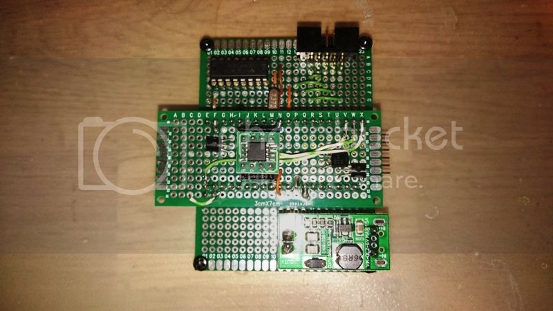
Hello i am building a DIY version of this scaled down stk500 programmer:
I have replaced the max662 with a small dc-dc step up, and the 741G125 with 2 transistors.
The question is abut the 74AHCT1G04DBV inverter i tried to invert the xtal1 signal with a transistor but no luck might be to fast signal or to crappy transistor, no idea.
The thing is if i just use the signal as it is and just pass it thru a 1k resistor its all working and i can program attiny13 in hvsp mode no problem.
The question what problems might i get if i use the signal as it is?? am i just lucky its all working? or will the programmer have problems when/if i try using it on bigger microprocessors ?
For HV programming I don't believe you need to buffer or invert the signals to any of the pins. You just need to control the 12V signal to the reset pin. For my method I'm just setting the fuses via HV and doing the other programming later via ISP: http://www.instructables.com/id/HV-Rescue-Simple/
maybe not with that code but i cant change this code, the code on that atmega8535 is the same code as on the stk500 development board so i cant change any of it, but on the plus side it is compatible with both arduino and Atmel Studio.
To use reset as IO i think you do need to control vtg as well as the 12v reset and sci (clock signal)
Yes, that is correct. My method is the quick and dirty way, and it is not compatible with anything. It is more of the brute force method to unlock the chip by programming the fuses.
To use reset as IO you can just use plain ISP programming (not HV programming). Set that fuse after you upload your program or bootloader via ISP. If you plan to allow further uploads, you must make sure the bootloader does not rely on the reset pin to work. To use that pin as a reset pin again and no longer use it as IO, or when you want to use ISP programming again, that is when you would need to do HV programming to unlock the chip.