I've been getting lots of noisy/ erratic readings on a load of potentiometers (using an UNO R3 and a MEGA 2560). After reading loads about it I think it's probably caused by the fact that I have not decoupled the power supply on either of the IC's. Neither have I used decoupling capacitors from the wiper to ground on any of the pots. From what I gather I need to be mounting a 0.1uF ceramic capacitor between Vcc and GND on each of the IC's and then I need 47uF caps on each of the pots.
So, my questions are...
Firstly, does all of this sound about right?
And if so...
A: Should I connect the 0.1uF caps to the Vcc and GND on the pin headers for each chip? or better still remove the headers altogether and solder the caps into the resulting holes?
B: Does the 47uF capacitor for the pots need to be ceramic as well or should it be electrolytic?
C: Where abouts should I connect the 47uF? Should I do this close to the pots or close to the board/ pins?
liamorourke:
Firstly, does all of this sound about right?
No.
You are obviously doing something wrong. You are talking about "mounting a 0.1uF ceramic capacitor between Vcc and GND on each of the IC's" and "on the pin headers for each chip" but what ICs are you talking about?
A picture (perfectly focussed and taken in daylight) might help in figuring out what on earth you are up to!
Does the 47uF capacitor for the pots need to be ceramic
You will have a job.
No it is fine to be an electrolytic.
A value of 47uF sounds very high for a pot wiper. If it is too big then there will be a delay between changing it and seeing the voltage change. You should not need one to get a stable reading. How unstable is the reading? Plus or minus one is normal and is in fact inevitable.
MarkT... I was wondering whether the types of cables I'm using was a problem. DO you have a link to the shielded cables which you mentioned please? It might pay me to try them out. Thanks
Grumpy_Mike The readings are quite unstable. In fact I am using: -
And it's still printing off a lot of random readings.
Anyway... am i right in thinking i need to connect the capacitors for the chips on the pin headers for each chip? I just can't think of anywhere else I'd put them. And do i need the capacitors for the pots close to the pots or close to the pins on the board?
I've got 10uF caps and 100uF caps (both electrolytic) so i'm going to try them and I'm using 0.1uF ceramics for the chips.
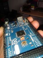
Hi... I have drawn out how i have the pots connected in this circuit diagram and then taken some photo's of how i have the 0.1uF ceramic pots connected to the chips via the pin headers on the board. It's a bit hard for me to take photo's of the way the pots are connected as they are all mounted into the enclosure which i am using. I have not yet tried connecting any capacitors near the pots as i want to work out what I'm doing wrong with the caps on the chips first.
I'm using single core copper 'bell wire' cable with pvc coating. I don't think it's shielded tho. Do you have a link to the shielded cabling you mentioned please? I've looked for some but can't find any.
Okay so after doing some more looking about I have found this: -
Which says that the chips on both the mega 2560 and the uno R3 already have decoupling capacitors in place. So I guess I was on completely the wrong lines with what I was trying. Ahh well... you live and learn i guess... luckily I didn't mess the pin headers on the 16u2 up beyond the point of being able to access dfu-mode.
By the way... MarkT... I answered your question with a question of my own earlier on in the thread. WHich was... could you please show me the shielded cables you mentioned as I think you might have a point in what you were saying. Sorry I didn't answer your question about length and type of cable then as I was busy trying to get my head around what i was doing wrong regarding decoupling.