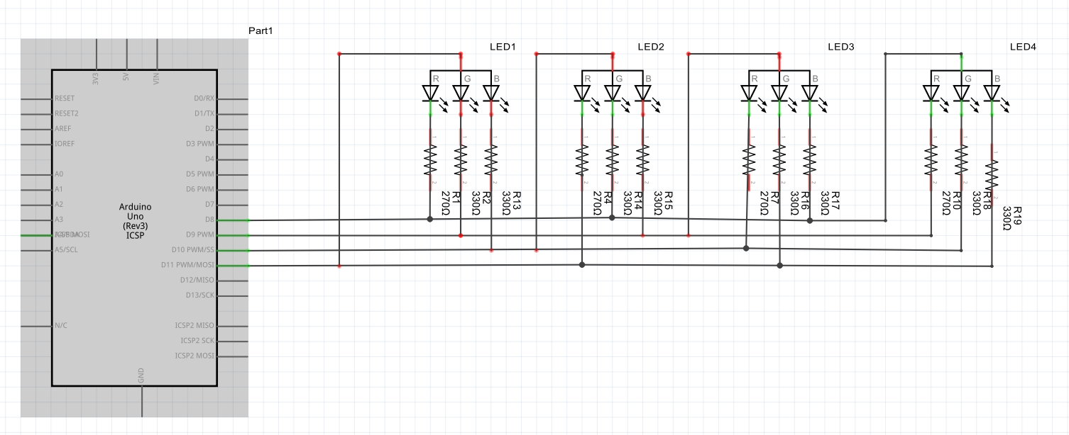
I am attempting to Charlieplex 4 RBGs but so far I'm not having any luck. Here is the code I have attempted to edit and the schematic (attached) on how I've wired them up. Any help is GREATLY appreciated!
#define CHARLIE_PINS  4
#define CHARLIE_FIRST 8

// Setup the memory
#define CHARLIE_COUNT CHARLIE_PINS*(CHARLIE_PINS-1)

// Charlie Level (0 = off, 255 = max)
#define CHARLIE_LOW    0
#define CHARLIE_HIGH 255

#define CHARLIE_OFF     0
#define CHARLIE_MAX   255

// Charlie Levels for anode/cathode pin-pairs
uint8_t charliePins[CHARLIE_PINS][CHARLIE_PINS];

#define CHARLIE_GREEN 0
#define CHARLIE_BLUE  1
#define CHARLIE_RED   2

//int charlieRGB[CHARLIE_PINS][3] = {{1, 2, 3}, {2, 3, 0}, {3, 0, 1}, {0, 1, 2}};
int charlieRGB[CHARLIE_PINS][3] = {{0, 1, 2}, {3, 0, 1}, {2, 3, 0}, {1, 2, 3}};

void charlieClear() {
  for(int i = 0; i < CHARLIE_PINS; i++) {
    for(int j = 0; j < CHARLIE_PINS; j++) {
      charliePins[i][j] = CHARLIE_OFF;
    }
  }
}

void charlieSetAll() {
  for(int i = 0; i < CHARLIE_PINS; i++) {
    for(int j = 0; j < CHARLIE_PINS; j++) {
      charliePins[i][j] = CHARLIE_MAX;
    }
  }
}

void charlieSetAllLevel(uint8_t level) {
  for(int i = 0; i < CHARLIE_PINS; i++) {
    for(int j = 0; j < CHARLIE_PINS; j++) {
      charliePins[i][j] = level;
    }
  }
}

void charlieWrite(int src, int dst, uint8_t level) {

  charliePins[src%CHARLIE_PINS][dst%CHARLIE_PINS] = level;

}

// current line displayed
int charlie_line = CHARLIE_PINS-1;

void charliePlexLine(uint8_t level) {

  // Disable last line displayed
  pinMode(CHARLIE_FIRST+charlie_line, INPUT);

  if(++charlie_line >= CHARLIE_PINS) charlie_line = 0;
  int i = charlie_line;
  int MasterPin = CHARLIE_FIRST+i;

  // Use others as follow pins (HIGH or INPUT)
  for(int j = 0; j < CHARLIE_PINS; j++) {
    int SlavePin = CHARLIE_FIRST+j;

    if(MasterPin != SlavePin) {
      if(charliePins[i][j] > level) {
        pinMode(SlavePin, OUTPUT);
        digitalWrite(SlavePin, LOW);
      } else {
        pinMode(SlavePin, INPUT);
      }
    }
  }
  pinMode(MasterPin, OUTPUT);
  digitalWrite(MasterPin, HIGH);
}

void charliePlex() {

  // Set one leadpin (LOW)
  for(int i = 0; i < CHARLIE_PINS; i++) {
    for(int j = 0; j < CHARLIE_MAX; j++) {
      charliePlexLine(j);
      delayMicroseconds(10);
    }
  }
}

// the setup routine runs once when you press reset:
void setup() {

}

void loop() {


  //Sample 1: First LED(0,1) "On"
  //
  charlieClear();
  //charlieWrite(4,1,CHARLIE_MAX);
  charlieWrite(2, charlieRGB[3][CHARLIE_GREEN],CHARLIE_MAX);
  charliePlex();


  /*
  // Sample 2: Dimm White
  for(int i = 0; i < 8; i++) {
    charlieSetAllLevel(1<<i);
    charliePlex();
  }
  for(int i = 7; i > -1; i--) {
    CHARLIE_PINS(1<<i);
    charliePlex();
  }
  //*/

  /*
  // Sample 3: Alternate the COLORS
  charlieClear();
  for(int i = 0; i < CHARLIE_PINS; i++) {
    charlieWrite(i, charlieRGB[i][CHARLIE_RED], CHARLIE_MAX);
    delay(500);
  }
  charliePlex();

  charlieClear();
  for(int i = 0; i < CHARLIE_PINS; i++) {
    charlieWrite(i, charlieRGB[i][CHARLIE_GREEN], CHARLIE_MAX);
    delay(500);
  }
  charliePlex();

  charlieClear();
  for(int i = 0; i < CHARLIE_PINS; i++) {
    charlieWrite(i, charlieRGB[i][CHARLIE_BLUE], CHARLIE_MAX);
    delay(500);
  }
  charliePlex();
  //*/

}