BigBobby:
Your schematic isn't 100% clear to me. For one thing, you have two nodes named Vout but I know they're not connected to each other.From the red arrows, however, it seems that you have a mode where you charge the battery through a FET/shunt which is controlled to provide a constant current?
Since your cells get ground through this FET/shunt you are putting a common mode signal at the inputs to your op amp. It sounds like this has the potential to cause the results you're seeing, although I don't have a good reason why it'd happen at the end of charge (when you'd expect the FET to be fully on).
Edited to Add: wait...no...if your FET was fully on at the end of charge, then you'd have 12V across your battery. I don't understand how your FET is controlled...
OK, I put some time into it and I understand now. If you don't mind, I added some labels to your schematic and reattached here. I'd post it as a picture, but my employer seems to block the free picture hosting sites (BTW - how little sense does it make that the forums will host the pictures as attachments, but not as pictures?).
Edited to add:
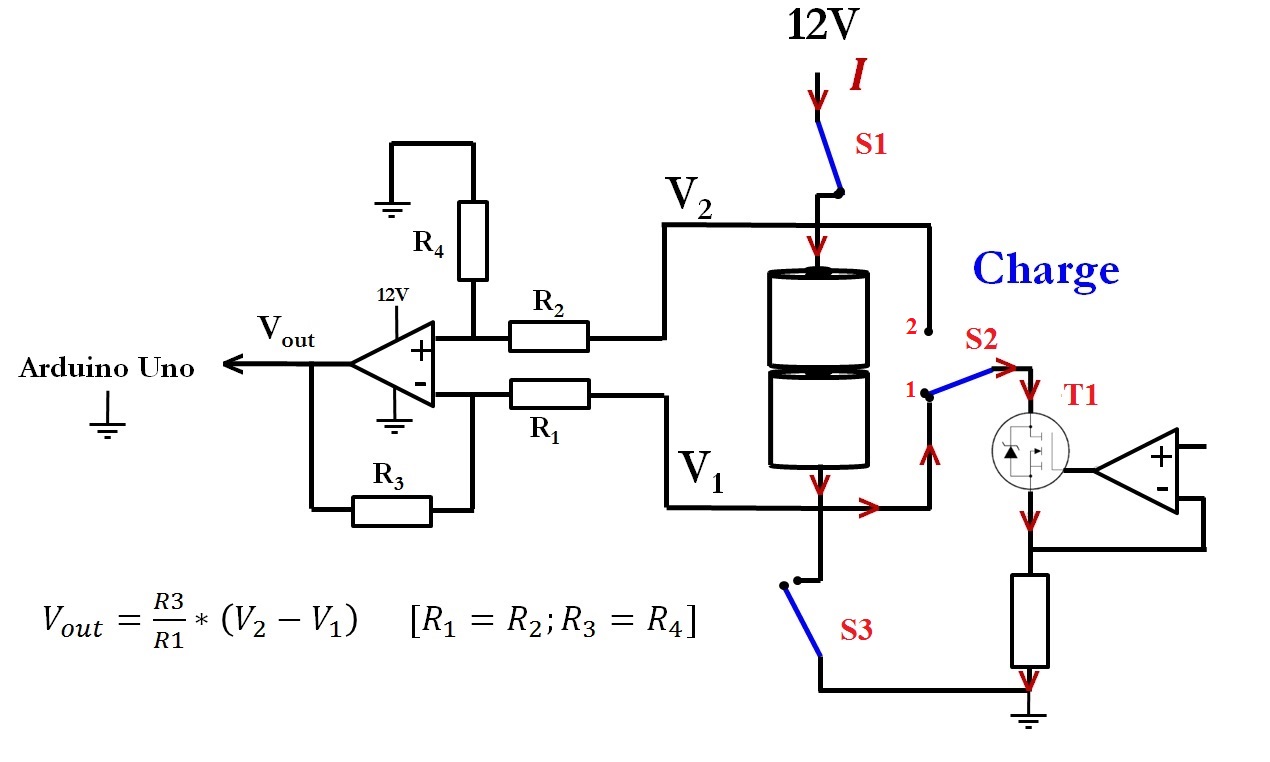
So if I understand your circuit correctly, T1 is a voltage controlled resistance that results in a constant current through your cells. When S1 is closed and S2 is in position 1, the cells are pulled up to 12V and T1 limits the charge current through the cells. When S3 is closed and S2 is in position 2, the cells are pulled down to GND and T1 limits the cells discharge current. Nice circuit.
It appears in your data you are always charging, which explains why your schematic shows the charging configuration. If your cells are balanced, they should be at ~1.23V. Are you sure they're both 1.23V? If they are, then they should be far away from end-of-charge where their impedance might do weird things.
It seems like your control for T1 must be unstable. As a test, when you see the A/D reading fluctuating like that, could you ground the + input to the amplifier controlling it to see if the A/D reading goes back to normal?
It also seems that the instability must be affecting your Arduino beyond just putting a high frequency on your cells. If your multimeter was just averaging the signal clean, it would be in the middle of the Arduino's samples where your Arduino samples are clearly higher. Possibly T1 being unstable could result in common mode signals getting through the op-amp, or maybe its ground currents aren't separated from the grounds of your op-amp and avr.
Seeing if the A/D readings go back to normal when T1 is forced off, however, would be the first step before figuring out how T1 is affecting your reading.