3 x HC-SR04 with LCD I2C

hi working on project for friend, it's for 36 meter wide boom sprayer
i got this basic coding working and running fine

cant work out how to add 2 more sensors, to have 3 total

tying get it display like this on screen and if one go pass +-25cm it add warning to that one line and keep distance there, once just got it working guess need add oms for long wiring loom.

eg... screen
01 Boom leveling
02 Left Side 50CM
03 Center 50CM
04 Right Side 50CM

i hope you guys can help me, i try do alot of googling but find no code works or do what i want

cheers

//Distance sensor
#define trigPin 12
#define echoPin 11
//Flashing LED on Arduino board
#define LEDPin 13
//LCD
#include <Wire.h>
#include <LCD.h>
#include <LiquidCrystal_I2C.h>
#define I2C_ADDR 0x27
#define BACKLIGHT_PIN 3
#define En_pin 2
#define Rw_pin 1
#define Rs_pin 0
#define D4_pin 4
#define D5_pin 5
#define D6_pin 6
#define D7_pin 7
int n = 1;
LiquidCrystal_I2C lcd(I2C_ADDR,En_pin,Rw_pin,Rs_pin,D4_pin,D5_pin,D6_pin,D7_pin);
void setup ()
{
Serial.begin(9600);
pinMode(trigPin, OUTPUT); //The transmit pin of the ultrasonic sensor
pinMode(echoPin, INPUT); //The receive pin of the ultrasonic sensor
pinMode(LEDPin, OUTPUT); //The LED of the Arduino
lcd.begin (20,4); //Size of LCD

// Switch on the backlight
lcd.setBacklightPin(BACKLIGHT_PIN,POSITIVE);
lcd.setBacklight(HIGH);
lcd.home (); // go home
}
void loop()
{
int duration, distance;
digitalWrite(trigPin, HIGH);
delayMicroseconds(100);
digitalWrite(trigPin, LOW);
duration = pulseIn(echoPin, HIGH);
distance =(duration/2) / 29.1;
lcd.clear();
lcd.setCursor(0,0);
lcd.print("Distance from object");
lcd.setCursor(0,1);
lcd.print(distance);
lcd.print("cm");
if (distance >=25)
if (distance <=75)
{
lcd.setCursor(0,4);
lcd.print("Safe Zone :)");
digitalWrite(LEDPin,HIGH);
delay(500);
digitalWrite(LEDPin,LOW);
delay(500);

}
else
{
lcd.clear();
lcd.setCursor(0,0);
lcd.print(" STEP AWAY!!!");
lcd.setCursor(0,1);
lcd.print(" STEP AWAY!!!");
lcd.setCursor(0,2);
lcd.print(" STEP AWAY!!!");
lcd.setCursor(0,3);
lcd.print(" STEP AWAY!!!");
}
}
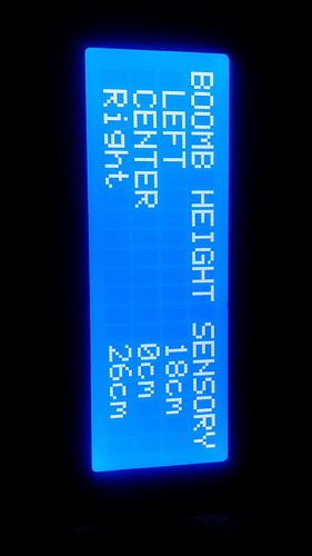
Anyone I take any ideas

Hello,

You should try to use the NewPing library, it was made for the HC-SR04 and it is pretty simple to use, also it comes with an example of how to read a lot of sensors at the same time. If you got any new problems just post here. =D

http://playground.arduino.cc/Code/NewPing

\o/

hey thanks for help, took abit i worked out how to get lcd to working in 15 sensors pings
and modify the file for 3 sensors.

all 3 sensors are working in serial mode AS 0,1,2
but on LCD screen i can only get sensor no: 2 showing only
not sure how to define witch sensor to it's own line

cheers

// ---------------------------------------------------------------------------
// This example code was used to successfully communicate with 15 ultrasonic sensors. You can adjust
// the number of sensors in your project by changing SONAR_NUM and the number of NewPing objects in the
// "sonar" array. You also need to change the pins for each sensor for the NewPing objects. Each sensor
// is pinged at 33ms intervals. So, one cycle of all sensors takes 495ms (33 * 15 = 495ms). The results
// are sent to the "oneSensorCycle" function which currently just displays the distance data. Your project
// would normally process the sensor results in this function (for example, decide if a robot needs to
// turn and call the turn function). Keep in mind this example is event-driven. Your complete sketch needs
// to be written so there's no "delay" commands and the loop() cycles at faster than a 33ms rate. If other
// processes take longer than 33ms, you'll need to increase PING_INTERVAL so it doesn't get behind.
// ---------------------------------------------------------------------------
#include <NewPing.h>

#define SONAR_NUM     3 // Number of sensors.
#define MAX_DISTANCE 500 // Maximum distance (in cm) to ping.
#define PING_INTERVAL 250 // Milliseconds between sensor pings (29ms is about the min to avoid cross-sensor echo).

unsigned long pingTimer[SONAR_NUM]; // Holds the times when the next ping should happen for each sensor.
unsigned int cm[SONAR_NUM];         // Where the ping distances are stored.
uint8_t currentSensor = 0;          // Keeps track of which sensor is active.

NewPing sonar[SONAR_NUM] = {     // Sensor object array.
  NewPing(12, 11, MAX_DISTANCE), // Each sensor's trigger pin, echo pin, and max distance to ping.
  NewPing(10, 9, MAX_DISTANCE),
  NewPing(6, 5, MAX_DISTANCE)
};
//LCD
#include <Wire.h>
#include <LCD.h>
#include <LiquidCrystal_I2C.h>

#define I2C_ADDR  0x27  // Define I2C Address where the PCF8574A is
#define BACKLIGHT_PIN   3
#define En_pin  2
#define Rw_pin  1
#define Rs_pin  0
#define D4_pin  4
#define D5_pin  5
#define D6_pin  6
#define D7_pin  7

int n = 1;

LiquidCrystal_I2C     lcd(I2C_ADDR,En_pin,Rw_pin,Rs_pin,D4_pin,D5_pin,D6_pin,D7_pin);

void setup() {
  Serial.begin(9600);
  pingTimer[0] = millis() + 1000;           // First ping starts at 75ms, gives time for the Arduino to chill before starting.
  for (uint8_t i = 1; i < SONAR_NUM; i++) // Set the starting time for each sensor.
    pingTimer[i] = pingTimer[i - 1] + PING_INTERVAL;


  Serial.begin(115200);
  
  lcd.begin (20,4);  //Size of LCD
 
// Switch on the backlight
  lcd.setBacklightPin(BACKLIGHT_PIN,POSITIVE);
  lcd.setBacklight(HIGH);
  lcd.home ();                // go home

}
void loop() {
  for (uint8_t i = 0; i < SONAR_NUM; i++) { // Loop through all the sensors.
    if (millis() >= pingTimer[i]) {         // Is it this sensor's time to ping?
      pingTimer[i] += PING_INTERVAL * SONAR_NUM;  // Set next time this sensor will be pinged.
      if (i == 0 && currentSensor == SONAR_NUM - 1) oneSensorCycle(); // Sensor ping cycle complete, do something with the results.
      sonar[currentSensor].timer_stop();          // Make sure previous timer is canceled before starting a new ping (insurance).
      currentSensor = i;                          // Sensor being accessed.
      cm[currentSensor] = 0;                      // Make distance zero in case there's no ping echo for this sensor.
      sonar[currentSensor].ping_timer(echoCheck); // Do the ping (processing continues, interrupt will call echoCheck to look for echo).
    }
  }
  // Other code that *DOESN'T* analyze ping results can go here.
}

void echoCheck() { // If ping received, set the sensor distance to array.
  if (sonar[currentSensor].check_timer())
    cm[currentSensor] = sonar[currentSensor].ping_result / US_ROUNDTRIP_CM;
}

void oneSensorCycle() { // Sensor ping cycle complete, do something with the results.
  // The following code would be replaced with your code that does something with the ping results.
  for (uint8_t i = 0; i < SONAR_NUM; i++) {
    Serial.print(i);
    Serial.print("=");
    Serial.print(cm[i]);
    Serial.print("cm ");
    lcd.clear();
    lcd.setCursor(4,0);
    lcd.print("BOOMB HEIGHT");
    lcd.setCursor(0,1);
    lcd.print(i);
    lcd.print("=");
    lcd.print(cm [i]);
    lcd.print("cm");
    lcd.setCursor(0,2);
    lcd.print(i);
    lcd.print("=");
    lcd.print(cm [i]);
    lcd.print("cm");
    lcd.setCursor(0,3);
    lcd.print(i);
    lcd.print("=");
    lcd.print(cm [i]);
    lcd.print("cm");
  }
  Serial.println();
}

_3_sensors_with_lcd_v0.1.ino (4.49 KB)

Hello, I modified some stuff in "void OneSensorCycle()" and Im not sure, but it should be something like:

void oneSensorCycle() { // Sensor ping cycle complete, do something with the results.
  // The following code would be replaced with your code that does something with the ping results.
  for (uint8_t i = 0; i < SONAR_NUM; i++) {
    if (i==0) {
      lcd.clear();
    }
    Serial.print(i);
    Serial.print("=");
    Serial.print(cm[i]);
    Serial.print("cm ");
    lcd.setCursor(4,0);
    lcd.print("BOOMB HEIGHT");
    lcd.setCursor(0,1+i);
    lcd.print(i);
    lcd.print("=");
    lcd.print(cm [i]);
    lcd.print("cm");
  }
  Serial.println();
}

On your code you were only seeing the readings of sensor 2 because it was the last sensor, so you were overwriting all previous readings. You should use "i" to change the lines otherwise you are writing a value in all lines... Also, I put an if there, so you know that when "i" is equal to 0, it is time to update the lcd, and only then you have to clear the lcd...

Any questions, just ask =D

cheers for help, modified code work good, now i know how it works i made some changes to it.

only got 1 question left not major 1 yet, 2 x sensors be 25 meters long cable and over be 20 meters long
do i need to add ohms law to code if YES not sure where or how??

Cheers

I would like to refresh the topic - did anyone make a level adjustment on 3 x HC-SR04 to such a sprayer beam, e.g. to maintain a constant level in the range of 40-60cm. Maybe there is a ready project somewhere?