im not quite shure which model of the NodeMCU ESP8266 ive got, but my Adruino IDE works with model ESP-12E which is included in this link.
Its an black ESP chip on an black breakout board.
Im trying to use the analog input A0. Many websites say that it uses an voltage of about 1V for analog reference. So ive builded a voltage divider from 3.3V to 1.1V. When i connect 1.1V to analog input pin A0 i get values of about 321.
So i connected the 3.3V Pin (messured 2.28V) to A0 Pin and still got values less then 1000.
Ive tried the same sketch as mentioned before with another black ESP8266 dev kit (CH340G wemos.cc LoLin new NodeMcu V3).
AnalogRead(A0) returns a value of 3 when A0 is connected to GND. Shouldnt it be 0???
Original NodeMCU Dev Kit returns values between 0 and 3 when A0 is connected to GND.
When i power on one of the dev kits there is always a new WLAN network, but my sketch does not start any network. Is that normal?
Does the WLAN network interfere with the analog readings?
When i connect the VU pin of LoLin dev kit to A0 i get an value of 1024. Also when i connect Vin pin of orig. NodeMCU dev kit to A0 i get a value of 1024. So analog reference has to be greater 3,3V.
How can i change it???
analogReference(INTERNAL) does not work.
I've literally just posted about this on the esp8266 forums. I've been banging my head about this for hours. Do you know how I can change the reference voltage?? I measured it with a multimeter and it's about 3.5V Also, where did you read about the voltage divider?
I'll continue in this thread with my follow up question:
I'm trying to get an lm35 (temperature sensor) to work with the analog pin on the nodemcu 1.0. I realise now that the voltage out (V_out) from the lm35 is not that arriving at the ADC pin on the esp, but rather V_adc = V_out * 100/320 (given the voltage divider).
So, if we have a V_out = 0.2V, the V_adc = 0.0625. We've basically scaled the V_out.
The LM35 datasheet says that the temperature changes by 1 deg C for each 10 mV. So, given that I've scaled the voltage, I'd have to scale the 10 mV/C to 10 * 100/320 mV/C, right? And the temperature reading should be V_adc * 1000 / (10 * 100 / 320)
I'm getting temperatures about 5 degrees higher than I would expect.. Here is my code for getting the temperature:
float getTemperature()
{
  int val = analogRead(TEMP);
  Serial.print("Analog: ");
  Serial.println(val);

  float mv = (val / 1024.0);
  Serial.print("V at analog: ");
  float vAtAnalog = val / 1024.0 * 3.3;

  mv = vAtAnalog * 1000;

  float cel = mv / (10.0 * (10.0/32.0));

  return cel;
}
Now, when I measured the with a potentiometer, I found the voltage at which the ADC pin gives a reading of 1024 is at about 3.5V. I'm not sure if this is related?
Can anyone see a problem / possible see whether I have a mistake in my code above. Any help is appreciated.
VADC doesn't really matter in this case. Vsensor = 3200 mV * analogRead(A0) / 1023.
The 50mV difference you are getting could just be an ADC or sensor calibration problem. You could test some temperatures, import the data in Excel, do a linear regression, and add a calibration factor and offset to your program.
Thank you Pieter. Makes sense. Regarding the ADC or sensor calibration, the sensor works good (I've tested on arduino and I've measured the voltage of the lm35 between v_out and gnd and everything works out about right). Given that, I imagine the ADC needs calibrating. How do I go about that?
As I type this, I thought that maybe I could plot the analogRead values against an output voltage (say using a potentiometer) and perform a linear regression, right?). I'll give that a shot and report back in a few hours.
Same problem here for the deviation. The reading of analogRead is always a bit smaller, so need a volt slightly larger than 3.3V to get 1024. It’s okay to do a calibration for one ESP module. Problem is, if it’s really the ADC which needs calibration, the offset may be different for each chip, and it’s not possible to calibrate each chip in the production.
Bilz:
.... I could plot the analogRead values against an output voltage (say using a potentiometer) and perform a linear regression, right?). I'll give that a shot and report back in a few hours.
did you do the regression?
What calibration factors did you come up with?
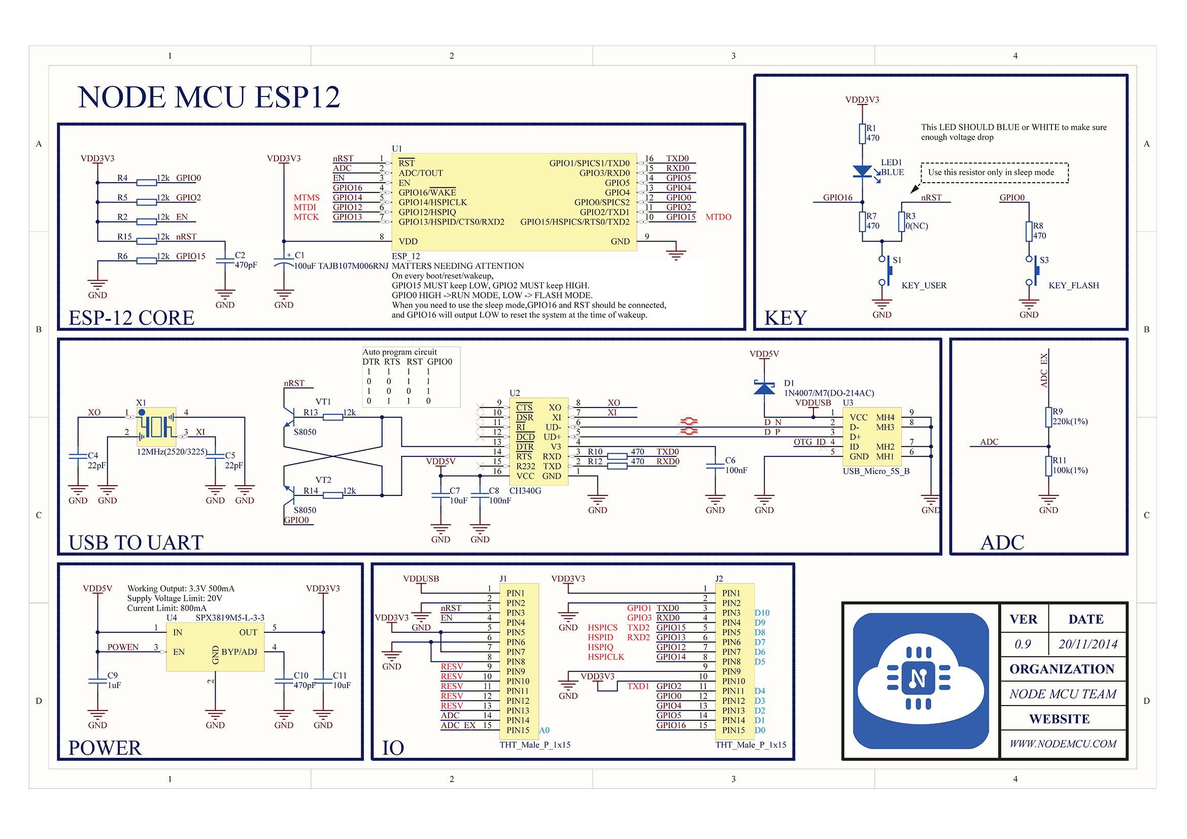
From the schematic in reply #4:
1 V * (100 kΩ + 220 kΩ) / 100 kΩ = 3.2 V
The maximum value you can get is 1023 (0x3FF), not 1024. However, you're right, the divisor is debatable. For example, the ATmega328P datasheet tells you to divide by 1024. I don't know if there's anything in the ESP8266 datasheet about it.
HiLetgo brand version from Amazon, with an AI-THINKER device.
3.0 volts on A0 reads as 991 units.
That leads to a max. 1023 reading of 3.1V.
How can this be so variable? It doesn't make sense at all. If the ADC divider resistors are so crap, surely all the other bits would be too and the thing just wouldn't work. The Uno ADC is pretty reliable.