Yeah, another time. But before telling me that there are many topics on this forum about that, read all the post.
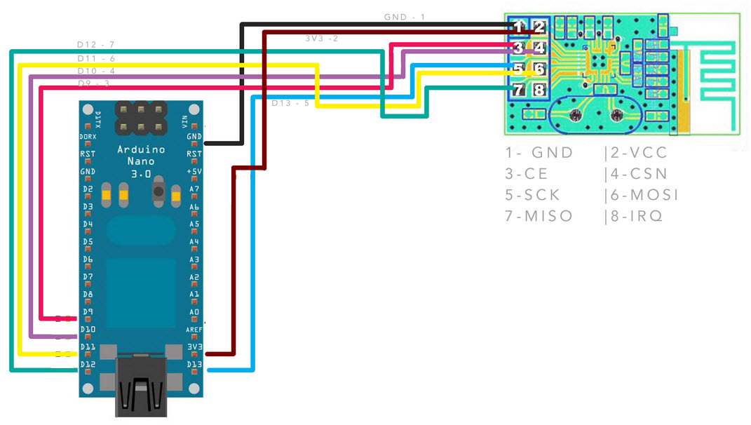
I have an Arduino Nano connected to an nRF24l01+ and an SD card reader in this way:
Now the problem. I try to upload just the CardInfo example in the SD library and all work fine, but if I try to upload a sketch that uses only the nRF24 the module doesn't receive the value, but if I remove the 5V pin from the SD card reader and I reboot the Nano, keeping all the other wires untouched, the reception work fine. So I suppose that is a hardware problem and not the software problem that I read many times on another post.
Did I make some mistakes? Any fix?
Many thanks!
The SD code:
/*
  SD card test

 This example shows how use the utility libraries on which the'
 SD library is based in order to get info about your SD card.
 Very useful for testing a card when you're not sure whether its working or not.

 The circuit:
  * SD card attached to SPI bus as follows:
 ** MOSI - pin 11 on Arduino Uno/Duemilanove/Diecimila
 ** MISO - pin 12 on Arduino Uno/Duemilanove/Diecimila
 ** CLK - pin 13 on Arduino Uno/Duemilanove/Diecimila
 ** CS - depends on your SD card shield or module.
 		Pin 4 used here for consistency with other Arduino examples


 created  28 Mar 2011
 by Limor Fried
 modified 9 Apr 2012
 by Tom Igoe
 */
// include the SD library:
#include <SPI.h>
#include <SD.h>

// set up variables using the SD utility library functions:
Sd2Card card;
SdVolume volume;
SdFile root;

// change this to match your SD shield or module;
// Arduino Ethernet shield: pin 4
// Adafruit SD shields and modules: pin 10
// Sparkfun SD shield: pin 8
const int chipSelect = 4;

void setup() {
  // Open serial communications and wait for port to open:
  Serial.begin(9600);
  while (!Serial) {
    ; // wait for serial port to connect. Needed for native USB port only
  }


  Serial.print("\nInitializing SD card...");

  // we'll use the initialization code from the utility libraries
  // since we're just testing if the card is working!
  if (!card.init(SPI_QUARTER_SPEED, chipSelect)) {
    Serial.println("initialization failed. Things to check:");
    Serial.println("* is a card inserted?");
    Serial.println("* is your wiring correct?");
    Serial.println("* did you change the chipSelect pin to match your shield or module?");
    return;
  } else {
    Serial.println("Wiring is correct and a card is present.");
  }

  // print the type of card
  Serial.print("\nCard type: ");
  switch (card.type()) {
    case SD_CARD_TYPE_SD1:
      Serial.println("SD1");
      break;
    case SD_CARD_TYPE_SD2:
      Serial.println("SD2");
      break;
    case SD_CARD_TYPE_SDHC:
      Serial.println("SDHC");
      break;
    default:
      Serial.println("Unknown");
  }

  // Now we will try to open the 'volume'/'partition' - it should be FAT16 or FAT32
  if (!volume.init(card)) {
    Serial.println("Could not find FAT16/FAT32 partition.\nMake sure you've formatted the card");
    return;
  }


  // print the type and size of the first FAT-type volume
  uint32_t volumesize;
  Serial.print("\nVolume type is FAT");
  Serial.println(volume.fatType(), DEC);
  Serial.println();

  volumesize = volume.blocksPerCluster();    // clusters are collections of blocks
  volumesize *= volume.clusterCount();       // we'll have a lot of clusters
  volumesize *= 512;                            // SD card blocks are always 512 bytes
  Serial.print("Volume size (bytes): ");
  Serial.println(volumesize);
  Serial.print("Volume size (Kbytes): ");
  volumesize /= 1024;
  Serial.println(volumesize);
  Serial.print("Volume size (Mbytes): ");
  volumesize /= 1024;
  Serial.println(volumesize);


  Serial.println("\nFiles found on the card (name, date and size in bytes): ");
  root.openRoot(volume);

  // list all files in the card with date and size
  root.ls(LS_R | LS_DATE | LS_SIZE);
}


void loop(void) {

}
The nRF24l01+ code:
#include <SPI.h>
#include "RF24.h"

RF24 radio(7,8);

unsigned long payload;
int var[2] = {};
bool temp_hum = true;
byte pipe;
float prova[2] = {1,6.9765};

// RX address (address of this module)
byte addresses[][6] = {"1Node", "2Node"};

void setup() {
	Serial.begin(115200);
	Serial.println("Boot OK");
	Serial.println("MODE: Receiver");

	radio.begin();

	// Settings
	radio.setPALevel(RF24_PA_MIN);// RF24_PA_MIN, RF24_PA_LOW, RF24_PA_HIGH RF24_PA_MAX

	radio.setChannel(108);
	radio.setDataRate(RF24_250KBPS); // Probably not working

	// Reading pipe with the address of this module
	radio.openReadingPipe(1,addresses[0]);

    radio.startListening();


}

void loop() {
	if(radio.available(&pipe)) {

      while (radio.available()) {                                   // While there is data ready
     	radio.read( &payload, sizeof(unsigned long) );             // Get the payload
      }
      if(temp_hum == true){
          var[0] = payload;
          Serial.print("Temperatura: ");
          Serial.print("Var[0]: ");
      	  Serial.println(var[0]);
      }
      if(temp_hum == false){
          var[1] = payload;
          Serial.print("Umidità: ");
          Serial.print("Var[1]: ");
      	  Serial.println(var[1]);
      }
      temp_hum = !temp_hum;
      Serial.print("Var[0]: ");
      Serial.println(var[0]);
      Serial.print("Var[1]: ");
      Serial.println(var[1]);


	}
}
I had a problem like this before i think this problem appears while using multiple SPI devices. I solved my problem by placing a diode between mosi pin of arduino and one of the modules mosi pin. You can try this and tell us wheter it works or not
I had a problem like this before i think this problem appears while using multiple SPI devices. I solved my problem by placing a diode between mosi pin of arduino and one of the modules mosi pin. You can try this and tell us wheter it works or not
I don't understand where I must place it and in what direction I must interrupt the current.
You have not posted the combined code that is causing a problem so it is a bit difficult to know what to say.
I don't have a combined code when I upload the nRF24 code simply the things don't work
Also, you are using pin 4 as CS (Chip Select) pin for the NRF24L01. What pin are you using for CS on the SD card? It cannot be the same.
I don't use CS pin 4 for the nRF24, it's not connected to that pin and I don't specify any pin 4 on the nRF24 code.
Eternyt:
I don't have a combined code when I upload the nRF24 code simply the things don't work
That sounds as if you cannot get the nRF24 code to work on its own without any reference to the SD Card. Is that correct?
I have been under the impression that you can get the nRF24 to work on its own and get the SD Card to work on its own but that when you tried a combined version it would not work.
That sounds as if you cannot get the nRF24 code to work on its own without any reference to the SD Card. Is that correct?
Yes, it is correct! When I try to use JUST the nRF24, using the code that I put in my first post under The nRF24l01+ code: the nRF24 doesn't work. If I remove the SD card reader or just the 5V pin from the circuit, (and I reboot) the nRF24 works well.
Your Fritzing diagram does not show any such connections to the Nano on pins 7 and 8. The text under the diagram mentions pin 4 as CS.
I'm sorry about my error. The image diagram shows that I connect pin 3 and 4 to D9 and D10 of the Nano, but I instead connect they to D7 and D8, as code RF24 radio(7,8); shows. Also, under the diagram, there are the wiring of the Nano and the SD, "SD --> Nano", in fact I use the cs pin 4 for the SD card.
That sounds as if you cannot get the nRF24 code to work on its own without any reference to the SD Card. Is that correct?
Yes, it is correct! When I try to use JUST the nRF24, using the code that I put in my first post under The nRF24l01+ code: the nRF24 doesn't work. If I remove the SD card reader or just the 5V pin from the circuit, (and I reboot) the nRF24 works well.
This is very confusing.
I asked if you had a problem getting the nRF24 to work on its own and you said that you have. Then in the next sentence you say that you have not. Which is correct?
Have you looked at the demo in my link in Reply #2
I have no problem to use the nRF24, if it's the only thing connect to SPI bus. If it is connect with the SD card reader, also if I don't use the SD card reader at all, the nRF24 doesn't work.
Sorry for the misunderstanding.
Eternyt:
I have no problem to use the nRF24, if it's the only thing connect to SPI bus. If it is connect with the SD card reader, also if I don't use the SD card reader at all, the nRF24 doesn't work.
Sorry for the misunderstanding.
OK. Now that that is clear, did you study my link?
The instruction for the Ethernet card (also SPI) give a warning about possible conflicts with the (inbuilt) SD card and a possible solution. I'm not sure how relevant it is here, but the solution seems simpe enough to be worth a try.:
Warning
This example doesn't require an SD card. If an SD card is inserted but not used, it is possbile for the sketch to hang, because pin 4 is used as SS (active low) of the SD and when not used it is configured as INPUT by default. Two possible solutions:
remove the SD card;
add these lines of code in the setup()
The instruction for the Ethernet card (also SPI) give a warning about possible conflicts with the (inbuilt) SD card and a possible solution. I'm not sure how relevant it is here, but the solution seems simpe enough to be worth a try.:
I try this fix, that is in line with the SPI protocol theory, but unfortunately doesn't work.
OK. Now that that is clear, did you study my link?
Yes, but before going to the software, it is better to make to work the two devices separately, is it?
If the two modules are FISICALY separately(so, for example, I use in a first moment the SD card, then I remove it from the breadboard and I wire the nRF24) with the two sketch I uploaded in my first post the two module work fine. If I wire all TOGETHER(so in the same breadboard there are the SD and the nRF24 module, both connected to the SPI busses), and I try to use the same two sketch, the nRF24 sketch doesn't work anymore. Then I suppose that is a hardware problem because I don't modify the sketch but just add the SD card reader to the electric circuit.
OK. Let me try to explain it in a way that I can understand. If you can't understand this please let me know.
You know how to write a program using an nRF24 and it works with nothing else connected to the Arduino.
You know how to write a program using an SD Card and it works with nothing else connected to the Arduino.
You have a problem when you have the nRF24 and the SD Card connected.
That last point is the reason I posted my link in Reply #2. I had no problem and I thought you would wish to try to see if your system would work the way mine worked. I am struggling to understand why we are at Reply #15 without that being tried.
If I remove the SD card reader from the circuit the serial monitor says something different:
testSDnRF24 Starting
Data Sent Message 0 Acknowledge data 0, 0
initialization failed!
done! ----------
Data Sent Message 1 Acknowledge data 0, 0
initialization failed!
done! ----------
Data Sent Message 2 Acknowledge data 0, 0
initialization failed!
done! ----------
Data Sent Message 3 Acknowledge data 0, 0
initialization failed!
done! ----------
Data Sent Message 4 Acknowledge data 0, 0
initialization failed!
done! ----------
Data Sent Message 5 Acknowledge data 0, 0
initialization failed!
done! ----------
Data Sent Message 6 Acknowledge data 0, 0
initialization failed!
done! ----------
Data Sent Message 7 Acknowledge data 0, 0
initialization failed!
done! ----------
Data Sent Message 8 Acknowledge data 0, 0
initialization failed!
done! ----------
Data Sent Message 9 Acknowledge data 3598, 3598
initialization failed!
done! ----------
Data Sent Message 0 Acknowledge data 1927, 1799
initialization failed!
done! ----------
Data Sent Message 1 Acknowledge data -1, -1
initialization failed!
done! ----------
Data Sent Message 2 Acknowledge but no data
initialization failed!
done! ----------
Data Sent Message 3 Acknowledge data 0, 0
initialization failed!
done! ----------
And if I start with the SD card insert in the circuit, than remove it, the monitor says:
Source File /mnt/sdb1/SGT-Prog/Arduino/SDandNRF/testSDnRF24.ino
testSDnRF24 Starting
Data Sent Message 0 Acknowledge data 3598, 3598
initialization failed!
done! ----------
Data Sent Message 1 Acknowledge data 0, 0
initialization failed!
done! ----------
Data Sent Message 2 Acknowledge data 0, 0
initialization failed!
done! ----------
Data Sent Message 3 Acknowledge data 0, 0
initialization failed!
done! ----------
Data Sent Message 4 Acknowledge data 0, 0
initialization failed!
done! ----------
Sorry, I had not recognized the output as I have not used that program very much.
IIRC the message "initialization failed!" pops up but does not mean anything. I believe the system works fine and the message can be ignored.
What files are actually on your SD Card? Can you print the directory listing using your PC?
When my program prints "done! ----------" it should mean that it has successfully accessed the SD Card.
Can you monitor the output of the Arduino with the other nRF24 in parallel with the Arduino with the SD Card so that you can see what the Arduino with the SD Card should be receiving.