Hey guys,
I'm relative new to the Arduino world. I've got this LTP-2B88AG-NB LED Matrix from the LITEON brand. And a Max7219 Driver for controlling it. I also have an Arduino UNO. As the thread title suggests i want to control the matrix with the MAX 7219 using the arduino.
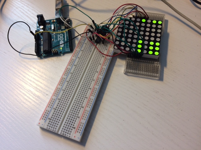
I tried to wire things up correctly on the breadboard several times but failed at having success. The lights of the arduino light up and moved but in some weird way which doesn't make any sense in regards to the sketch I am using. I'll post the sketch here and some pictures concerning the wiring, for your further understanding.
My first question is are all pins on an 8x8 led matrix components ordered the same way on every 8x8 matrix from every brand? They all look the same but is the order of the pins on the back of the matrix also the same? The following video would indicate it..

After a longer rather period of time i found it but I still can't seem to get things up and running.
In this video it seems that all led matrixes would be built the same and one could just lay them on your table in a certain position to know how the pin numbers are ordered, am I actually right with this? ![]()
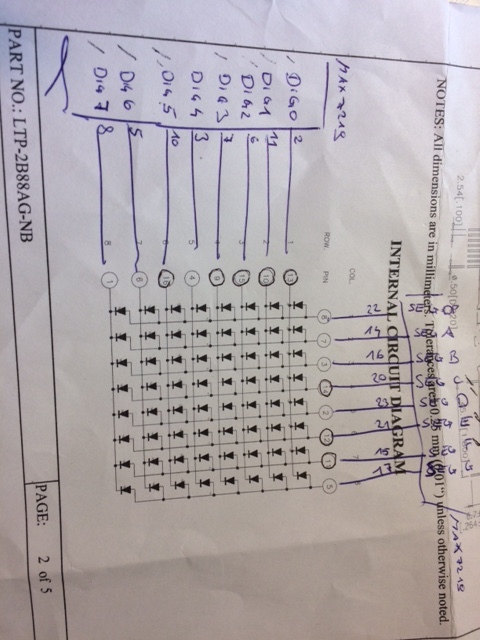
I am doing this project for a subject in university some fellow students gave me the sheet which i attached to this post.
Am I reading it right as it indicates to connect the pin numbers near the graphic on the sheet to each port of the MAX7219? I have done that, but it just won't give me the sequence of flashing LEDS as outlined in the sketch.
My routing from the Max7219 to the arduino is the following:
int DIN = 12;
int CS = 11;
int CLK = 10;
int GND = GND;
int V+ = 5V;
I am using this LCD Demo Matrix Code:
#include <LedControl.h>

int DIN = 12;
int CS =  11;
int CLK = 10;

byte e[8]=     {0x7C,0x7C,0x60,0x7C,0x7C,0x60,0x7C,0x7C};
byte d[8]=     {0x78,0x7C,0x66,0x66,0x66,0x66,0x7C,0x78};
byte u[8]=     {0x66,0x66,0x66,0x66,0x66,0x66,0x7E,0x7E};
byte c[8]=     {0x7E,0x7E,0x60,0x60,0x60,0x60,0x7E,0x7E};
byte eight[8]= {0x7E,0x7E,0x66,0x7E,0x7E,0x66,0x7E,0x7E};
byte s[8]=     {0x7E,0x7C,0x60,0x7C,0x3E,0x06,0x3E,0x7E};
byte dot[8]=   {0x00,0x00,0x00,0x00,0x00,0x00,0x18,0x18};
byte o[8]=     {0x7E,0x7E,0x66,0x66,0x66,0x66,0x7E,0x7E};
byte m[8]=     {0xE7,0xFF,0xFF,0xDB,0xDB,0xDB,0xC3,0xC3};

LedControl lc=LedControl(DIN,CLK,CS,0);

void setup(){
lc.shutdown(0,false);       //The MAX72XX is in power-saving mode on startup
lc.setIntensity(0,15);      // Set the brightness to maximum value
lc.clearDisplay(0);         // and clear the display
}

void loop(){

   byte smile[8]=   {0x3C,0x42,0xA5,0x81,0xA5,0x99,0x42,0x3C};
   byte neutral[8]= {0x3C,0x42,0xA5,0x81,0xBD,0x81,0x42,0x3C};
   byte frown[8]=   {0x3C,0x42,0xA5,0x81,0x99,0xA5,0x42,0x3C};

   printByte(smile);

   delay(1000);

   printByte(neutral);

   delay(1000);

   printByte(frown);

   delay(1000);

   printEduc8s();

   lc.clearDisplay(0);

   delay(1000);
}

void printEduc8s()
{
 printByte(e);
 delay(1000);
 printByte(d);
 delay(1000);
 printByte(u);
 delay(1000);
 printByte(c);
 delay(1000);
 printByte(eight);
 delay(1000);
 printByte(s);
 delay(1000);
 printByte(dot);
 delay(1000);
 printByte(c);
 delay(1000);
 printByte(o);
 delay(1000);
 printByte(m);
 delay(1000);
}

void printByte(byte character [])
{
 int i = 0;
 for(i=0;i<8;i++)
 {
   lc.setRow(0,i,character[i]);
 }
}
And the LedControl library I added to my arduino via the library manager it is from Eberhard Fahle.
I hope this post is somewhat clear to you if somethings not clear please ask. As already mentioned I am attaching pictures of the whole builup, the "cheat-sheet" and the code. I hope someone can help.. ![]()
I may already thank you in advance for your help!