For a project (a very large midi controller) I need a lot of inputs and outputs. I need about:
60 analog inputs for potentiometers
180 digital inputs for buttons
250 digital outputs for LED's
I know this is a ridiculous amount of inputs and outputs...
For the analog inputs I want to use 74hc4067 multiplexers. For the digital inputs I am thinking about using multiplexers or shift registers. For the digital outputs I am thinking about using shift registers too.
I have some questions however:
If I am using a lot of multiplexers at the same time, will the arduino be fast enough to read all the inputs without a too long delay?
And when using shift registers for the digital inputs?
When I am using shift registers for the outputs, will the arduino be fast enough to switch all the leds on and off without a too long delay?
Will I be able to switch all the leds on when I am using shift registers, or will this burn the arduino or shift registers?
Will shift registers and multiplexers work? If not, are there any other (affordable) options?
Thank you for your answer. I read some articles and using matrices looks like a great solution (it will not use a lot of current either). Do you know if multiplexers for all the inputs will work? Or will this be too slow with so many buttons and potentiometer?
I'd go with analog switch such as DG406 for the pots, 16:1 swithing.
With 4 parts, can cleanly switch 64 pots into 4 analog inputs with 4 control lines to select the channel being read.
180 buttons, 14x14 matrix with Keypad.h library should work with 28 IO pins. http://playground.arduino.cc/Code/Keypad
"Current version
3.0 2012-07-12 - Mark Stanley : Made library multi-keypress by default. "
I've not done one that big. You could set up and test responsiveness by faking inputs with a couple wires.
MAX7219 for the LEDs for sure, offloads a lot of multiplexing from the processor. Good price for them at www.taydaelectronics.com, $3.09 last I knew. Buttons, other parts there too.
Thank you for the usefull suggestions! So for the leds I'm definitely going to use the max7219 chips and multiplexers for the pots. Using a matrix for the buttons looks like a good solution, but there is one problem: the arduino I wanted to use doesn't have 28 input pins. I wanted to use a arduino with an atmega 32u4 chip, since this chip supports midi over USB. Can I use multiplexers for the 28 inputs or is it better to use an arduino mega and built a midi output circuit? Or are there any chips like the max7219 for inputs?
You could build build the key matrix scanner circuit with shift registers. A 74hc595 for driving the rows and 3 x 74hc1645 for reading the columns for example. Or 4 x pcf8475 I/o expanders.
For your buttons, will they be pressed one at a time, or will they be used more like a computer keyboard?
One technique commonly used by Sony (I repair lots of their gear) is to use a switched reference supply through a resistance ladder. You can design a series of resistors with values designed to create analog voltages when a button is pressed, which shorts one point in the ladder down to zero volts. The simplest example is just one switch and two resistors. The resistors are in series across the power supply, and are of equal value. The common connection between the resistors is sent to an anolog ADC input on the Arduino. When no button is pressed the voltage is VCC / 2. When the button, which is connected across the lower resistor, is pressed, the input becomes ZERO volts.
This can be expanded for two buttons using three equal resistors in series, by splitting the lower resistor into two and strapping another button across the new lower resistor in the chain. No buttons closed, and the ADC input voltage is 2 x VCC/3 (ie two-thirds of VCC). Press button one, which shorts the two lower resistors to ground and the input voltage is again zero, but press the second button and the voltage at input becomes VCC/2 again. This can continue until the voltage difference between steps becomes unreliable for accurate determining by the ADC, but in theory it allow for up to 1023 buttons with a 10-bit ADC.
In practice a chain of same-value resistors is not suitable unless the number of buttons is small. Practical applications use a non-linear ladder so that the voltage generated at the reference point becomes more linear and simpler to read by the ADC. I am sure there is a simple mathematical function to work out the resistor value ratios, but I am a non-mathematician I am afraid to say.
Hope this helps. Jim.
PS - one downfall of this technique is when worn switches become ohmic. Users of in-line remote controls on their earphone cables will have experienced this, when pressing play is incorrectly interpreted as next track or some other function. Or worse still, record!
It will work if the resistors are binary weighted, but that limits the number of buttons on a line. I would use the MCP23S17 there are 16 programmable I/O per chip and you can monitor any input being pressed by a single output line ( called and interrupt line ).
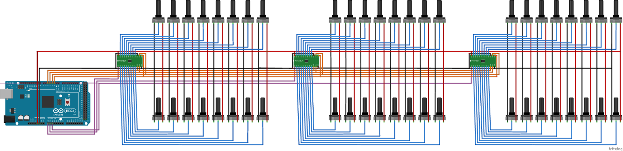
Thank you all for the help. Because I don't really completely understand how the resistor chains work, I decided to use button matrices and an arduino mega. I have made some schematics diagrams:
one for the buttons. The buttons will be connected to the female headers on the pcb's.
one for the pots.
one for the leds. The leds will be connected to the female headers on the pcb's.
Does it looks okay, or are there any mistakes in my schematics diagrams?
Use Reply, then scroll down below the box and use "Attachments and other options" to attach your whatever so we see them. The website image.ibb.co is blocked for many of us.
ryanaukes:
What happens when I the technique you described and press 2 (or more) buttons of the same chain? This won't work, right?
Because each button is connected to ground, if more than one button is pressed the one higher up the chain overrules any below. There is no conflict, as all resistors and buttons below are connected to ground on both ends of that part of the chain. It really is simple. In fact, I would bet most of the domestic audio and video gear with push button control uses this technique.
Oh, no, you didn't! Those are not schematics. They are "diagrams" but they don't count as schematics. Fritzing does have a schematic view. You can switch to that but you will need to do some tidying to make them presentable.
Do those '4067 breakout boards have bypass caps? If not, you will need to add them. Other than that, your circuits look ok (as far as I can tell until you can give us proper schematics).
Use Reply, then scroll down below the box and use "Attachments and other options" to attach your whatever so we see them. The website image.ibb.co is blocked for many of us.
I changed it
Do those '4067 breakout boards have bypass caps? If not, you will need to add them.
They don't have bypass capacitors I think. However, all the tutorials I have read about the 74HC4067 chips didn't use any capacitors either. How do I know what value I need and do I really need them?