Multiplexing SPI LINES

Hi,

I got 5 MFRC55 (RFID) reader. When I hook them up together I get a lot of noise on the line. Sometimes it works and sometimes it doesn't.

So it's suggested to use multiplexing on the line. I quote:

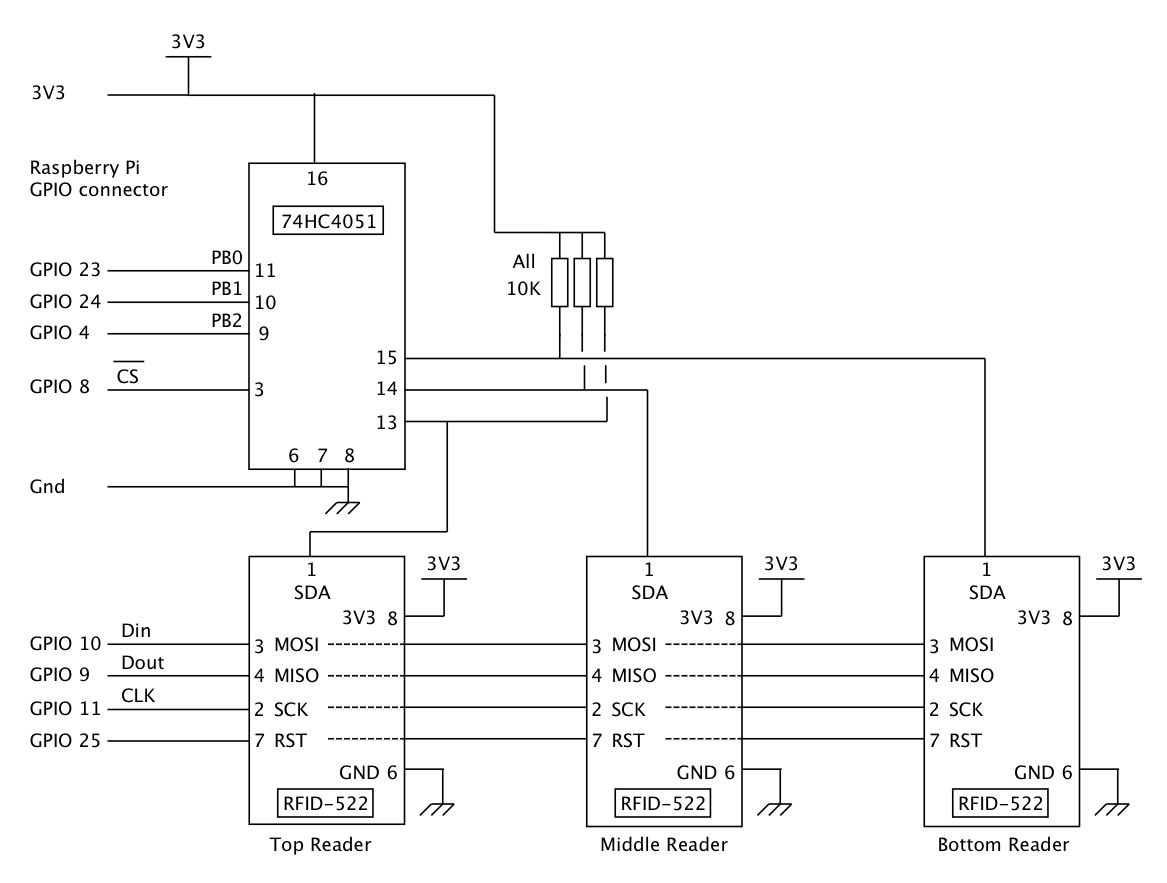
"The solution is to use multiplexers for each arduino pin: SCK, MOSI, MISO, then bring every card's SDA pin to GND so they are all selected. Then you initiate just one class object, and start it for each card in turn. That way you can have as many RFID readers in communication as you want, limited only by the multiplexers. "

So I tried that.

I attached a CD4051 Multiplexer on one line. In this case the SCK line and tried to attach 1 reader. It failt. The Arduino does not see the RFID reader. So I am a bit stuck here.

  • I connected the SCK line to port 0 on the CD4051.
  • If I replace the RFID line on the multiplexer with a LED, the LED works fine. So the multiplexer is connected in the way it should be.
  • I can get the RFID to work connected directly to the Arduino.

I feel like i'm close to getting it to work, but I am a bit stuck on what to try next.

/*
 * --------------------------------------------------------------------------------------------------------------------
 * Example sketch/program showing how to read data from a PICC to serial.
 * --------------------------------------------------------------------------------------------------------------------
 * This is a MFRC522 library example; for further details and other examples see: https://github.com/miguelbalboa/rfid
 * 
 * Example sketch/program showing how to read data from a PICC (that is: a RFID Tag or Card) using a MFRC522 based RFID
 * Reader on the Arduino SPI interface.
 * 
 * When the Arduino and the MFRC522 module are connected (see the pin layout below), load this sketch into Arduino IDE
 * then verify/compile and upload it. To see the output: use Tools, Serial Monitor of the IDE (hit Ctrl+Shft+M). When
 * you present a PICC (that is: a RFID Tag or Card) at reading distance of the MFRC522 Reader/PCD, the serial output
 * will show the ID/UID, type and any data blocks it can read. Note: you may see "Timeout in communication" messages
 * when removing the PICC from reading distance too early.
 * 
 * If your reader supports it, this sketch/program will read all the PICCs presented (that is: multiple tag reading).
 * So if you stack two or more PICCs on top of each other and present them to the reader, it will first output all
 * details of the first and then the next PICC. Note that this may take some time as all data blocks are dumped, so
 * keep the PICCs at reading distance until complete.
 * 
 * @license Released into the public domain.
 * 
 * Typical pin layout used:
 * -----------------------------------------------------------------------------------------
 *             MFRC522      Arduino       Arduino   Arduino    Arduino          Arduino
 *             Reader/PCD   Uno/101       Mega      Nano v3    Leonardo/Micro   Pro Micro
 * Signal      Pin          Pin           Pin       Pin        Pin              Pin
 * -----------------------------------------------------------------------------------------
 * RST/Reset   RST          9             5         D9         RESET/ICSP-5     RST
 * SPI SS      SDA(SS)      10            53        D10        10               10
 * SPI MOSI    MOSI         11 / ICSP-4   51        D11        ICSP-4           16
 * SPI MISO    MISO         12 / ICSP-1   50        D12        ICSP-1           14
 * SPI SCK     SCK          13 / ICSP-3   52        D13        ICSP-3           15
 */

#include <SPI.h>
#include <MFRC522.h>

#define RST_PIN         9          // Configurable, see typical pin layout above
#define SS_PIN          53         // Configurable, see typical pin layout above

int addressA = 1;
int addressB = 2;
int addressC = 3;

int A = 0;      //Address pin A
int B = 0;      //Address pin B
int C = 0;      //Address pin C


MFRC522 mfrc522(SS_PIN, RST_PIN);  // Create MFRC522 instance

void setup() {
	Serial.begin(9600);		// Initialize serial communications with the PC
	while (!Serial);		// Do nothing if no serial port is opened (added for Arduinos based on ATMEGA32U4)
  
  pinMode(addressA, OUTPUT);
  pinMode(addressB, OUTPUT);
  pinMode(addressC, OUTPUT);
  multiplex();
  
	SPI.begin();			// Init SPI bus
	mfrc522.PCD_Init();		// Init MFRC522
	mfrc522.PCD_DumpVersionToSerial();	// Show details of PCD - MFRC522 Card Reader details
	Serial.println(F("Scan PICC to see UID, SAK, type, and data blocks..."));
}

void loop() {
  multiplex();
	// Look for new cards
	if ( ! mfrc522.PICC_IsNewCardPresent()) {
		return;
	}

	// Select one of the cards
	if ( ! mfrc522.PICC_ReadCardSerial()) {
		return;
	}

	// Dump debug info about the card; PICC_HaltA() is automatically called
	mfrc522.PICC_DumpToSerial(&(mfrc522.uid));
}

void multiplex()
{
    A = bitRead(0,0); //Take first bit from binary value of i channel.
    B = bitRead(0,1); //Take second bit from binary value of i channel.
    C = bitRead(0,2); //Take third bit from value of i channel.

    //Write address to mux
    digitalWrite(addressA, A);
    digitalWrite(addressB, B);
    digitalWrite(addressC, C);

   //digitalWrite(outputpin2, 1);
}

dont know if the mux fools you..,
but this:

t.... and start it for each card in turn.

knut_ny:
dont know if the mux fools you..,
but this:

It shouldn't matter when I only connect one reader to the mux right?

U're right

The solution is to use multiplexers for each arduino pin: SCK, MOSI, MISO, then bring every card's SDA pin to GND so they are all selected.

That is crap. All the lines can be common apart from the SDA, that is the one you must put through the multiplexer.

This is a circuit I used on a Raspberry Pi, it will also work for any 3V3 Arduino. If you have a 5V Arduino you must put a potential divider on each output pin from the Arduino to the reader. That is all the pins except Dout. And power the multiplexer with 5V.

Grumpy_Mike:
That is crap. All the lines can be common apart from the SDA, that is the one you must put through the multiplexer.

This is a circuit I used on a Raspberry Pi, it will also work for any 3V3 Arduino. If you have a 5V Arduino you must put a potential divider on each output pin from the Arduino to the reader. That is all the pins except Dout. And power the multiplexer with 5V.

Thank you for your answer. Indeed I can get 3 rfid reader to work reliably with common lines. But when I add the 4th or the 5th rfid reader then sometimes it works and sometimes it doesn't work.

The total cable length is also around 20 meters in total. So that's also a source of the problem. That's why I started looking into multiplexing.

If I cannot work the multiplexing out, then i'm going to use 2 Arduino's and share the output between the ARduino's with a RF24L01+ chip.

The total cable length is also around 20 meters in total. So that's also a source of the problem.

It is indeed and it is not a problem multiplexers will solve

then i'm going to use 2 Arduino's and share the output between the ARduino's with a RF24L01+ chip.

Always a bad idea to use more than one Arduino on a project.

You need buffering on those lines, use a AMLS2631A to send a signal and then use a AMLS2632A on the far end to receive it. They are differential drivers / receivers and communicate each signal over a pair of twisted wires. You get four buffers in a package.

Grumpy_Mike:
It is indeed and it is not a problem multiplexers will solve
Always a bad idea to use more than one Arduino on a project.

You need buffering on those lines, use a AMLS2631A to send a signal and then use a AMLS2632A on the far end to receive it. They are differential drivers / receivers and communicate each signal over a pair of twisted wires. You get four buffers in a package.

I was on vacation for a few days so it took me a little longer to reply back.

I assume you talk about the 26LS31/26LS32 differential drivers/receivers. Because when I google for the types you mention I don't get any results.

Can I just hook them up like mentioned in the datasheet? Or do I need to write some extra coding?

Datasheet

Could you explain why it would be a bad idea to use 2 Arduino's connected with each other trough serial. I can imagine that it would not be the most efficient way, but it could also be a solution to the problems I am having.

The second Arduino would only have to send a "ok" when the proper card is scanned. It doesn't need to send a "false" when the wrong card is scanned.

Sorry dyslexia kicking in I meant AM26LS31A and AM26LS32A.

Can I just hook them up like mentioned in the datasheet

Yes.

Or do I need to write some extra coding?

No.

but it could also be a solution to the problems I am having.

No

Could you explain why it would be a bad idea to use 2 Arduino's

Because there is simply no need to have two, you can do all you want with one.

Grumpy_Mike:
Sorry dyslexia kicking in I meant AM26LS31A and AM26LS32A.
Yes.
No.
No
Because there is simply no need to have two, you can do all you want with one.

Thank you for the clarification.

Is the following assumption correct?

  • I have 5 readers and 1 Arduino
  • MISO, MOSI, CLK need buffering on the lines. SS does not.
  • Do I need to place the DS26LS31 or the DS26LS32 near the Arduino? My guess would be the DS26LS32 because that's the receiver.

  • If so then does every RFID reader need a DS26LS31? Or do I need to place 1 in the center and make every MISO, MOSI, CLK line common and connect it to only one DS26LS31?

  • Or do I need to place 5 DS26LS31 near the RFID and then make the lines common and connect them to one DS26LS32? Am I right in thinking this is the approach?

Datasheet DS26LS31

Datasheet DS26LS32

  • MISO, MOSI, CLK need buffering on the lines.

Yes

SS does not.

No.

If they are remote then the MOSI, CLK SS need the transmit buffer at the Arduino end and the receiver buffer at the reader end. The MISO needs buffering with a transmitter at the reader end and a receiver at the Arduino end.

In addition because the Arduino is 5V and the reader is 3v3 then the MOSI, CLK SS need cutting down to 3v3 between the receiver and the reader.

If so then does every RFID reader need a DS26LS31?

It depends on how far your readers are apart as well as remote from the Arduino.
You have not explained your setup apart from saying

The total cable length is also around 20 meters in total.

Grumpy_Mike:
YesNo.

If they are remote then the MOSI, CLK SS need the transmit buffer at the Arduino end and the receiver buffer at the reader end. The MISO needs buffering with a transmitter at the reader end and a receiver at the Arduino end.

In addition because the Arduino is 5V and the reader is 3v3 then the MOSI, CLK SS need cutting down to 3v3 between the receiver and the reader.
It depends on how far your readers are apart as well as remote from the Arduino.
You have not explained your setup apart from saying

I am trying to build a puzzle for a friend.

  • 5 MFRC522 modules are hooked to a wall. The modules are 50cm-1m apart from each other.
  • 1 Arduino will be put behind the ceiling.
  • To every module there will be a CAT5E cable running with every cable being around 5-7 meters in length. So the total length will be around 25-35 meters in total. I cannot put a wire horizontally from one RFID reader to another. The cable needs to go up to the ceiling first.
  • 1 RFID card will be programmed to be connected to 1 Reader. So there will be 5 RFID cards in total.
  • If the right card is held before the right reader a LED will light up. So there will be 5 LEDS in total.

That is the setup. If I forgot to tell you other information that you need please let me know.

/edit

Let's say I make some adjustments and make a cable run horizontally between all the RFID readers. That will be a cable about 7 meters in length. Then I connect every RFID to that cable with another 50cm cable. So 5 readers will be around 2,5 meter extra cable.

Then my total cable length will be around 9,5-10 meters. Will that help a lot?

Tricky, you are on the edge of needing buffers but I wouldn't entirely rule out it working without. I would try it just by itself first.

Grumpy_Mike:
Tricky, you are on the edge of needing buffers but I wouldn't entirely rule out it working without. I would try it just by itself first.

Ok I will try to find out if it possible to shorten the wires.

In the mean while I am also going to order the differential drivers / receivers.

So if I understand it correctly I need to following extra parts:

MOSI + CLK + SS

2x transmitter (placed near the Arduino) >> Room for 8 lines to buffer >> 1x MOSI + 1x CLK + 5x SS
5x receiver (placed near the 5 RFID)

The lines need to become common before going into the transmitter (is this correct?)

MISO

1x receiver (placed near the Arduino)
5x transmitter (placed near the 5 RFID)

The lines need to become common before going into the receiver (is this correct?)

Is this correct?

I am a bit confused can you draw a schematic or block diagram of what you propose.

Grumpy_Mike:
I am a bit confused can you draw a schematic or block diagram of what you propose.

I hope it makes sense. I never have created a schematic before. I noticed I forgot to connect the reset line, but that doesn't matter for this schematic.

The schematic is in the attachment.

Well I supposed I asked for it, it is not much clearer. For future reference make all wires horizontal or vertical and don't have wires going through components.

Now chips IC1 to 5 why are you only using one buffer in each chip. You have four identical buffers in each chip so that should simplify things. BUT you can not common the outputs of the buffers. I think you are getting mixed up by me saying common the MISO lines. You can only do this with the signal on the readers, this is because the chip enable line on the readers makes the signal on the readers tri-state when that chip is not being addressed. Once the signal goes through a buffer you loose that tri-state and they become normal signals that you can not join together because they are outputs. You will need separate receive buffers and you need to connect them to either different input pins or you need to multiplex them into one.

When drawing a schematic their is no need to show a chip with the pins in the physical order you can order them as you like as long as you number them.

Also with things like the buffers you can show each buffer individually, not all four joined together to make the flow simpler. The whole point of a schematic is to show the interconnections and signal flow. This does not mean a lot of rectangles with wires flying all over the place.

Grumpy_Mike:
Well I supposed I asked for it, it is not much clearer. For future reference make all wires horizontal or vertical and don't have wires going through components.

Now chips IC1 to 5 why are you only using one buffer in each chip. You have four identical buffers in each chip so that should simplify things. BUT you can not common the outputs of the buffers. I think you are getting mixed up by me saying common the MISO lines. You can only do this with the signal on the readers, this is because the chip enable line on the readers makes the signal on the readers tri-state when that chip is not being addressed. Once the signal goes through a buffer you loose that tri-state and they become normal signals that you can not join together because they are outputs. You will need separate receive buffers and you need to connect them to either different input pins or you need to multiplex them into one.

When drawing a schematic their is no need to show a chip with the pins in the physical order you can order them as you like as long as you number them.

Also with things like the buffers you can show each buffer individually, not all four joined together to make the flow simpler. The whole point of a schematic is to show the interconnections and signal flow. This does not mean a lot of rectangles with wires flying all over the place.

Thanks you for your time and help. I really appreciate it. I ordered the line drivers and will try them out when I got the time. I don't have much experience in this and figuring this out will be harder than I originally thought. I will just make a prototype on a breadboard and test until I can get it to work.

In the mean while I will use 2 Arduino's connected through serial. That's something I can get working :wink:

Grumpy_Mike:
That is crap. All the lines can be common apart from the SDA, that is the one you must put through the multiplexer.

This is a circuit I used on a Raspberry Pi, it will also work for any 3V3 Arduino. If you have a 5V Arduino you must put a potential divider on each output pin from the Arduino to the reader. That is all the pins except Dout. And power the multiplexer with 5V.

i think this is answer for my project. i use 3 rfid too on my project, but i dont have much experience with this. so, i want to ask you about this. have u try it on arduino? and do you have sourcecode to multiplexing rfid with arduino? thank you, im sorry for my english..

have u try it on arduino?

No but their is absolutely no way it will not work on a 3V3 Arduino.

If you have a 5V Arduino then you have to cut the 5V signals from the Arduino down to 3V3 with potential dividers before you feed them to this circuit. You have to do that anyway if you want to use these readers on a 5V Arduino.

do you have sourcecode to multiplexing rfid with arduino

No but it is simply a matter of putting the binary address of the reader you want to talk to on pins 11, 10 & 9 of the 4051. So just three digital write instructions to select the reader.