I have scoured the interwebs and I cannot seem to figure out what is wrong with my MIDI-IN circuit. I've tried just about every Arduino project for MIDI-IN and even used a oscilliscope to find out what is wrong. I've tried an amplified circuit and the Midi Manufacture's Association setup, and niether seem to work. What seems to be happening is that the signal never seems to cross the optocoupler (a 6N138).
I will post a picture of my circuits when I get the chance so that you can tell me if I am connecting anything wrong:

Other hardware specs:
- Genuino Arduino Board Kit from SparkFun
- Midi Source is from iPod G5 through an iConnectivity iConnectMIDI1L
If you have any additional questions, I will be glad to answer them. I need this fixed as soon as possible as I need this working for a college senior design project and I have gotten little to nowhere in the past month because of this issue. All advice and help is appreciated 
Regards,
Midimistro
I will post a picture of my circuits when I get the chance so that you can tell me if I am connecting anything wrong.
It sounds like you keep making the same mistake with everything you try. But until we can see what you are doing we can't even begin to speculate. We need a picture of your circuit a schematic of what it is and the software you are using and what you are connecting to it.
Read the how to use this forum sticky post.
Grumpy_Mike:
We need a picture of your circuit a schematic of what it is and the software you are using and what you are connecting to it.
See new link... Had to fight Arduino Forum limits just to get it able for you to see it cause the photo's data size exceeds 1280KB, and that's the lowest resolution I can post at :P.
Ok let me add a little punctuation into that advice:-
We need a picture of your circuit, a schematic of what it is, and the software you are using, and what you are connecting to it.
Well one out of three is a start.
What are those chips?
How do they connect to the Arduino?
What is your software?
What actually happens?
What is your code?
In general while a MIDI receive circuit will work on a 5V or 3V3 system. A MIDI transmit circuit on a 3V3 processor needs some form of amplification to get to work with the 5V based MIDI system.
Posting images, see image guide
There are 3 Circuits on the board:
-
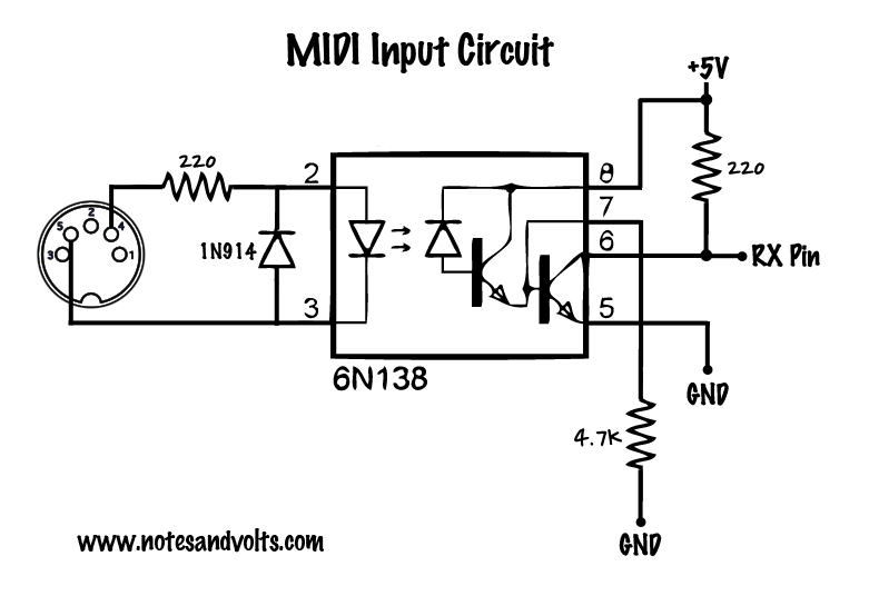
On the Left, a MIDI IN Circuit based on the following Schematic (tested with both resistor values for 3.3V and 5V; The chip in this circuit is a 6N138):
The signal does not cross the 6N138.
I've also tested this circuit with a 1N4148 Diode in place of the 1N194.
-
The circuit in the Middle is a MIDI OUT circuit, and it works fine regardless of which voltage I use from the Arduino.
-
On the right is an amplified version (this was the closest I could get the schematic to , however all the parts are labeled appropriately):
3.3V Circuit on Schematic.com
The signal does not cross the 6N138.
I also did some research about the Arduino and MIDI In and found out that the 6N137 supposedly is supposed to work better than the 6N138 and is less prone to damage (which may be the cause of my circuit issue), so that is the next thing I am going to try.
As for the software and code I use, I use the standard Arduino MIDI Library provided on GitHub and the most recent version of the Arduino IDE.
As for what happens, I can get a signal by hooking up Ch1 of an oscilloscope to pins 2 and 3 of the the 6N138 in the midi schematic posted above, but when I put CH2 on any mix of 5, 6, or 8 of the 6N138, all I get is a constant HIGH voltage of whatever voltage I have going into pin 8 (though pin 6 comes out .1V less, but is still constant)
Circuit 3:-
The minimum operating voltage of the TL071 is 6V, you are only feeding it with 3 volts. There is no common reference between the input signals and the TL071 so even if the supply voltage was correct then it still wouldn't work.
Circuit 2:-
I can't see this, where is it? But as you say it works there is less of an issue
Circuit 1:-
I am concerned that you say
tested with both resistor values for 3.3V and 5V
The resistor values should be the same. However on a 3V3 system the 220R RX pull up resistor should go to the 3V3 supply not 5V. Lets hope you have not blown it. I would also disconnect the resistor on pin 7 and let it float.
Finally what way round is that connector. Their is often some confusion as to if you are looking at the holes the plug connects to or the back of the socket, you should try swapping these two input connectors over.
As a final note I always use the 6N139, a quick look at the data sheet doesn't show much of a difference between the two.
This is my version of a 5V MIDI shield:- http://www.thebox.myzen.co.uk/Hardware/MIDI_Shield.html
I can get a signal by hooking up Ch1 of an oscilloscope to pins 2 and 3 of the the 6N138 in the midi schematic posted above, but when I put CH2 on any mix of 5, 6, or 8 of the 6N138, all I get is a constant HIGH voltage of whatever voltage I have going into pin 8
You can't do that because there is no common connection between the MIDI input and the output of the opto. You should only measure one side at a time and move the scope's ground over.
Grumpy_Mike:
You can't do that because there is no common connection between the MIDI input and the output of the opto. You should only measure one side at a time and move the scope's ground over.
Yes I can cause each channel on the oscilloscope that I am using can has its own ground.
Grumpy_Mike:
Circuit 3:-
The minimum operating voltage of the TL071 is 6V, you are only feeding it with 3 volts. There is no common reference between the input signals and the TL071 so even if the supply voltage was correct then it still wouldn't work.
The TL071 works fine and is doing its job, even at 3.3V. Its the 6N138 that giving me grief.
Grumpy_Mike:
Circuit 1:-
I am concerned that you sayThe resistor values should be the same. However on a 3V3 system the 220R RX pull up resistor should go to the 3V3 supply not 5V. Lets hope you have not blown it. I would also disconnect the resistor on pin 7 and let it float.
Finally what way round is that connector. Their is often some confusion as to if you are looking at the holes the plug connects to or the back of the socket, you should try swapping these two input connectors over.
- So what you are saying is that regardless the voltage, the circuit layout should stay the same?
- The connector is an Adafruit MIDI DIN. However, in that regard, I did try flipping the direction relative to the 6n138 and still no dice
So what you are saying is that regardless the voltage, the circuit layout should stay the same?
Yes.
However, in that regard, I did try flipping the direction relative to the 6n138 and still no dice
Sounds like you have either faulty components or wiring. Is it on a solderless bread board?
The TL071 works fine and is doing its job, even at 3.3V.
From the data sheet:-
They don't say it if they don't mean it.
Yes I can cause each channel on the oscilloscope that I am using can has its own ground.
What is the model number and make of this scope? I have never come across a scope like that.
Come to think about I can't see how that would work. Normally all the ground connections on scope probes are electricity at the same potential, namely mains ground.