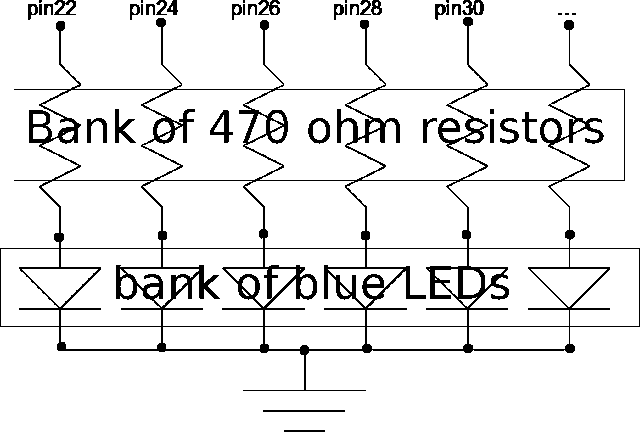
I've tweaked the emf meter sketch found here:
adapting the blogger's circuit diagram:

using the below sketch on the Arduino UNO:
/*
  Hertz based electric field meter for Arduino.
  Free and Open Source Apache License release.
  Apache license is free and open source and simply requires notification
  to the author before derrivitive work.  adamoutler at hotmail dotcom.
  Based on a sketch found here:
  http://www.hyundaiaftermarket.org/forum/index.php?/blog/3/entry-26-arduino-emf-meter/
  and circuit diagram here:
  http://i236.photobucket.com/albums/ff111/DrivingTibNaked/leds.gif
*/

//A note on HZ, if you notice meter oscillations on a known steady
//  signal increase or decrease hertz by 1.  The oscillations are
//  caused when the signals are in near-perfect resonance.
float FrequencyToMonitor=59; //hertz


//setup pins
#define ANTENNA 10 //antenna pin
//10 LEDs on 16 different pins
// int LEDPin[]={ 2, 3, 4, 5, 6, 7, 8, 9, 11, 12 } ;
int LEDPin[]={ 12, 11, 9, 8, 7, 6, 5, 4, 3, 2 } ;
int LEDCount=10;    //number of LEDs

//setup initial global values
int LEDCounter=0;               //initial value of LEDs to display
int HalfPeriodMicroseconds=0;// initial value of halfwavelength

/*
   SETUP defines pins and performs POT(Power On Test) on LEDs
*/
void setup()  {
   double HalfPeriod=((1/FrequencyToMonitor)*.5);   //Half-period in seconds from frequency
   HalfPeriodMicroseconds=int(1000000*HalfPeriod);  //Convert period seconds to microseconds integer

   pinMode(ANTENNA, INPUT);                   //set antenna pin
   for (int Pin=0; Pin < LEDCount; Pin++)  { //initialize each LED
    pinMode(LEDPin[Pin], OUTPUT);
    digitalWrite(LEDPin[Pin], HIGH);          //Turn the LED on
    delay(100);
    digitalWrite(LEDPin[Pin], LOW);          //Turn the LED back off
   }
   swingLEDs();         //perform LED check to verify LED functionality
}


/*
   LOOP checks for value of antenna to go high and then low
   if change is seen, then 2 LEDs are lit, otherwise total number
   of LEDS are decreased.  This allows for a magentic effect when
   near the field.
   http://www.hyundaiaftermarket.org/forum/index.php?/blog/3/entry-26-arduino-emf-meter/
*/
void loop(){
   int ANTENNAValue=0;    //sets and resets ANTENNAValue
   int OldANTENNAValue=0; // as well as OldANTENNAValue


   for ( int Pass=0; Pass < 4; Pass++ )  {//take 4 readings
    ANTENNAValue=digitalRead(ANTENNA);    //   from the antenna
    if ( ( ANTENNAValue == HIGH ) && ( OldANTENNAValue == LOW ) ) {
        incrementLED(); //If a change is detected increase twice
        incrementLED(); //   4 passes means 3 changes total
    } else if ( ( ANTENNAValue ==  LOW ) && ( OldANTENNAValue == HIGH ) ) {
        incrementLED(); //   This makes the meter rise by
        incrementLED(); //   a total factor of  2 and
    } else {
        decrementLED(); //   if there is no change it falls by 1
    }
        OldANTENNAValue=ANTENNAValue; //Log old value for next pass
        delayMicroseconds(HalfPeriodMicroseconds);  // half-wave pause before next reading
   }
   delayMicroseconds(HalfPeriodMicroseconds); //visual delay between reading passes
   delayMicroseconds(HalfPeriodMicroseconds); //twice to avoid extremely long numbers
}


/*
FUNCTION swingLEDs tests the LEDs by lighting
them up sequentially.  Each LED is brought high
then low twice.
*/
void swingLEDs(){
        for (int Pin=0; Pin < LEDCount; Pin++)  {
        digitalWrite(LEDPin[Pin], HIGH);  // light LEDs from left to right
        delay(50);
   }
   for (int Pin=0; Pin < LEDCount; Pin++)  {
        digitalWrite(LEDPin[Pin], LOW);   // clear LEDs from left to right
        delay(50);
   }
   for (int Pin=LEDCount; Pin > -1; Pin--)  {
        digitalWrite(LEDPin[Pin], HIGH);  // light LEDs from right to left
        delay(50);
   }
   for (int Pin=LEDCount; Pin > -1; Pin--)  {
        digitalWrite(LEDPin[Pin], LOW);   // clear LEDs from right to left
        delay(50);
   }
}

/*
FUNCTION incrementLED increases the number
of LEDs lit by 1.
*/
void incrementLED(){
    if ( LEDCounter <  LEDCount  - 1  ){ LEDCounter++;} //if not max increase
    digitalWrite(LEDPin[LEDCounter], HIGH); //light new LED
}

/*
FUNCTION decrementLED decreases the number
of LEDs lit by 1.
*/
void decrementLED(){
   digitalWrite(LEDPin[LEDCounter], LOW); //turn off current LED
   if ( LEDCounter >= 0 ){ LEDCounter-- ;} // if not zero, decrease
}
Everything works as expected. Woohoo!
I noticed an odd thing when I first tried this int LEDPin[]={ 11, 10, 9, 8, 7, 6, 5, 4, 3, 2 } ;for my pins. Pin 10 would light up at the same time as pin 2. I cannot say why, so that was the main reason why pin 10 became my choice for the antenna. Also, I chose pin 10 for the antenna because Pins, 13 and 0 didn't seen to work well for this. I didn't try pin 1. Pins 12 and 11 Use blue LED's. Pins 9 and 8 are green. 7 and 6 are yellow. 5 and 4 are orange. 3 and 2 are red.
Dumb Noob Questions:
-
Why would pin 10 light up at the same time as pin 2 when used as shown in the one-line code LEDPin[] array as above, and why in general do some of the digital pins not work as expected? For instance, I couldn't get pin 13 to act as an antenna, but it's fine as an LED.
-
I tried two different size antennae (3" and 6") but could distinguish little difference in sensitivity. What is a good antenna length for sensing something at about 60Hz? Why aren't we using an analog-in for the antenna?
-
I notice that I had to isolate the UNO from the AC power supply when connecting the UNO via USB to the computer in order to get a valid reading. But when I put my hands near the antenna (within six inches), I get a high reading. It doesn't make sense that the human body should be cycling at 60 Hz. What's really happening?
-
It looks like the fluctuation matches my heart beat, but I'm guessing this is really the oscillation the original blogger noted about in the sketch. Correct?
-
I've used 220 Ohm resistors instead of the 440. Might this affect sensitivity? I'm guessing not. But if so, how?
Cheers.