Resistor for each LED or one for many (for MIDI controller/looper)?

Hello, this is my first post in the Arduino forums, so forgive me if I'm doing it wrong.. :slight_smile:

I bought an arduino a couple months ago and have done some of the tutorials, and have learned enough to 'get started' on my first project (which will be kinda advanced, but has individual components that are simple and straightforward)... Bought a Mega later as I need a lot more I/O and memory than the Uno provides..

But first, I need to answer some questions I have about general wiring of the project..

it will involve several relays and several LED's...

My first issue is the LED's...

Is it wiser to put a separate LED on the "+" lead of each diode, or can I use a single Resistor on the "-" side which will be a common for all LED's (IOW, tie all the "-" leads of multiple LEDs together, and then place a single resistor in series with that common connection and ground)? If the latter, how do I size the resistor..

What is standard OP for this scenario?

Thanks!
Mark

Resistor per LED.
Doesn't matter which end you put it.

Thank you...

Curious (for general knowledge), why this is better than a single Resistor for all LEDs?

Because then the current through the LED will depend on how many LEDs are on!

This means that if you only use one resistor then the brightness of the LEDs that are on will change according to how many LEDs are on. The more that are on the dimmer each one will be.

Even though the LED's are all wired in parallel? In my mind, I'm thinking that the only place the current would change is through the resistor.. IOW, that each LED would still see just the resistor (being the only thing in series with the individual LED)

But all of this is why I asked.. :wink:

Or is it an issue of adding more LEDs in parallel changes the amount of voltage that the resistor drops within the circuit (changes the dividing point of total drop)? IOW, as more current passes through the resistor, it drops less of the network voltage, and the individual LEDs increase in brightness as each LED is turned on?

Thanks,
Mark

For clarification, attaching an image depicting the two scenarios..

common vs individual resistor.jpg

Volt drop across a LED is fairly constant, e.g. ~2volt for a small red LED.
If you connect two LEDs in parallel, that volt drop across the two LEDs is still 2volt.

That results in the same volt drop across the resistor (~3volt) with one, or with more LEDs.
Same voltage, so the same current through the resistor, independent of the number of LEDs.
That fixed resistor current can be used by one, or shared by many LEDs.

Different coloured LEDs have different working voltages. A blue LED is about 3.3volt.
If you put a red LED and a blue LED in parallel, then all the current will flow through the red LED.
Leo..

Even though the LED's are all wired in parallel?

Yes, especially as the LEDs are in parallel. If they were in serese then you would only need on resistor for all of them.

In my mind, I'm thinking .....

No electricity does not work like that.

Or is it an issue of adding more LEDs in parallel changes the amount of voltage that the resistor drops within the circuit

The more current through an LED the more voltage is dropped across it. So more LEDs on, mean more current, which means more voltage dropped across the resistor. This means less current for each LED.

Grumpy_Mike:
The more current through an LED the more voltage is dropped across it. So more LEDs on, mean more current, which means more voltage dropped across the resistor. This means less current for each LED.

That's kinda what I thought might be the case.. But I really don't understand how LEDs are measured resistance wise.. I guess I kinda saw them as diodes (switches), but I know that can't be right, otherwise wiring them directly across a voltage source would create a short circuit, meaning they must have 'some' resistance, but it sounds like their resistance changes according to the power passing through them?

But I really don't understand how LEDs are measured resistance wise.

Simple they are not.

The "effective resistance" of an LED changes with the current through it. Where as a resistor has a constant resistance no matter what current is put through it.

Resistance is not a good concept to use here.

Search google image for "LED I-V curve"

That's a plot of the current through the LED vs the voltage drop.

In contrast, for a resistor, the IV "curve" would be a straight line.

Actually, it's all coming back to me now.. :wink:

Even if the LEDs all had constant resistance, adding more branches of the parallel circuit would change the dynamics of the overall series circuit, moving the dividing point of the voltage dividing network...

2 LEDs @ 100 ohms each in parallel = 50 ohms seen by the single resistor meaning that across a 100 ohm feeder resistor, the LEDs would be dropping a third of the total voltage...

4 LEDs at 100 ohms each in parallel = 25 ohms seen by the feeder resistor, meaning that the LEDs would now be drawing only a fifth of the total voltage..

So each time another LED is added, they all get dimmer...

Thanks, it's clear as mud in my bean now! :grin:
Mark

MountainCraft:
Thanks, it's clear as mud in my bean now! :grin:
Mark

You're supposed to put beans into mud, not the other way around.... but that's a matter for a gardening forum...

Curious (for general knowledge), why this is better than a single Resistor for all LEDs?

It depends on how they are wired & controlled, but it' related to [u]Ohm's Law[/u] and [u]Kirchhoff's Laws[/u].

You may already know Ohm's Law, and it's pretty simple to understand as long as you "get" that resistance is the resistance to current flow... Higher resistance = less current (and higher voltage means more current).

But, Kirchhoff's Laws (which describe how voltages & currents divide and sum in series & parallel circuits) require a bit more study, especially if you haven't taken a basic electronics class.

Further complicating things is the fact that LEDs are non-linear... Their resistance changes (drastically) with voltage, so although Ohm's Law is true (it's a law of nature) it's difficult to apply to LEDs.

...But, without all of those "laws" you can think of the old water-flow analog* where water-flow in a pipe represents current and water pressure represents voltage. A small-skinny pipe is a high resistance and a fat pipe has less resistance.

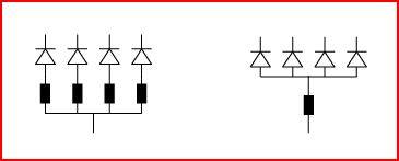
You CAN put multiple LEDs in series with one resistor as long as you have enough voltage. If you have 3 LEDs (at about 2V each) a resistor, and 12V power supply, it works perfectly because in series the same current flows through all of the LEDs and through the resistor, and you get (about) 2V across each LED with 6V "remaining" across the resistor. But of course, you can't control them separately because the same current is flowing through all of them.

You can wire them in parallel (with one series resistor) but there a couple of issues... The current is limited by the resistor and is split between the two LED. But because of that non-linearity and manufacturing variations the current may not split evenly and one LED may be brighter than the other. You can often get-away with it, but it's "bad practice".

It is possible to control the parallel LEDs separately but since the current is controlled by the resistor, the same current flows when one LED is turned-off and all of current goes-through the other LED and it gets brighter... No good!

* A couple of things about the water analogy - If you cut a water pipe you get zero-resistance and water flow-out everywhere. If you cut a wire you get infinite resistance and no current flows. And with water, nothing bad happens when there is no resistance (except maybe a flood :smiley: ) but with electronics, zero-resistance is a "short circuit", too much current flows and stuff burns-up (or a circuit breaker blows, etc.).

So to control the brightness of an LED do I just take it's max rated current draw, and then use that to calculate how much current flowing through a resistor provides that much current (ignoring the internal resistance of the LED)?

The fact that the LEDs change resistance according to the power supplied to them is confusing from a design standpoint... Obviously, thinking of them as regular ole light bulbs doesn't cut it... How is all that calculated?

Thanks,
Mark

DVDdoug:
You can wire them in parallel (with one series resistor) but there a couple of issues... The current is limited by the resistor and is split between the two LED. But because of that non-linearity and manufacturing variations the current may not split evenly and one LED may be brighter than the other. You can often get-away with it, but it's "bad practice".

I now understand that it's not worth the trouble, and I might as well just solder a resistor to the end of each LED, cover it with heat shrink and be done with it...

Thanks,
Mark

LEDs, like diodes, have a fairly constant voltdrop across.
Subtract that Vf (working voltage) from the supply voltage.
The remaining voltage drops across the CL resistor.
With that voltage you can calculate resistor value for a certain desired LED current.

Note that you don't have to use max LED current (20mA for most small LEDs).
Most of the modern ones are perfectly happy with 1-10mA.

You bought a Mega, with many pins.
I hope not for 'many LEDs'.
Processors do have pin/port/package current limitations.
Leo..

Okay then, all that considered;

The LEDs I will be using are spec'd as follows

Red = 1.8-2.4v, 20ma
Blue = 3.0-3.4v, 20ma
Yellow = 2.0-2.2v, 20ma
Green = 3.0-3.4v, 20ma
RGB = 1.9-3.4v, 40ma

I don't care if the blue is a different brightness than the reds (as long as they are reasonably similar) and so on, but I want all the reds to be the same, and all the blues to be the same, etc.

Is 300ohms a good value for the resistors (LED's directly fed from the Arduino Mega's digital outputs)? They're gonna be hard to replace once permanently installed (silicon glued to a removable faceplate), so my only two requirements are that they be easily seen from 6 feet away, and that they last long time...

Or maybe a better question is, what is a good value for the individual resistors to achieve those
two goals? I would prefer to be able to see them in broad daylight, but more often than not it will be artificial room light or dark (on stage), but the broad daylight thing needs to be subservient to the longevity thing...

Thanks,
Mark

Is 300ohms a good value for the resistors

Yes.

It would help if you got your terms right.
Voltage is across, current is through. Power is the product ( like in multiplying voltage and current ) is nether across nor through.

Or maybe a better question is, what is a good value for the individual resistors to achieve those
two goals?

You should only put the maximum rated current through an LED. Whether that is bright enough for a specific purpose is dependent on how efficient the LEDs are at converting current to light. You find that in the data sheet.

Grumpy_Mike:
Yes.

Thanks!

Grumpy_Mike:
It would help if you got your terms right.
Voltage is across, current is through. Power is the product ( like in multiplying voltage and current ) is nether across nor through.

LOL.. I know all this.. I have a pretty decent background with these concepts as I was an avionics tech in the military and also civilian side (but ICs were just coming out back then, so much of this stuff was not in existence then), and then later as a Low voltage wireman (Large commerical life safety/fire alarm systems, nurse call systems, etc.), and then later an inside wireman (including process control at refineries, etc.), but it's been a long time since I had to 'think' about this stuff seeing as so much of it is just automatic for me, so thanks for the reminder..

I've always wondered how current/voltage/power of LEDs is considered in a circuit, so this gets me all pointed in the right direction...

Thanks again to all for the explanations...

Next, I gotta tally up all the things that will be going on with this project and figure out how big of a power supply I need for it (for another thread), but at least I can start wiring up all the switches and LEDs now, and start playing with programming the basics for this beast...

I better head over to the 'feasibility' forum too, and make sure the Mega 2560 is capable of doing all that I need this thing to do... :slight_smile:

Thanks,
Mark