Hello please help me.
Arduino nano + NRF24L01. Robin ardunio Testing Program with the NRF is OK.
Arduino nano with Mini Pro bootloader for battery power (3.7V) + NRF. Test program will list 0x08 everywhere.
Please, give me an advice. Thank you
Post the program YOU are using for your test and post a sample of the output. If you are using a pair of Tx and Rx programs post both of them.
Also make a pencil drawing showing how you have everything connected and post a photo of the drawing.
3.7v is too much for an nRF24.
Test Sketch
// 18 Mar 2018 - simple program to verify connection between Arduino
// and nRF24L01+
// This program does NOT attempt any communication with another nRF24
#include <SPI.h>
#include <nRF24L01.h>
#include <RF24.h>
#include <printf.h>
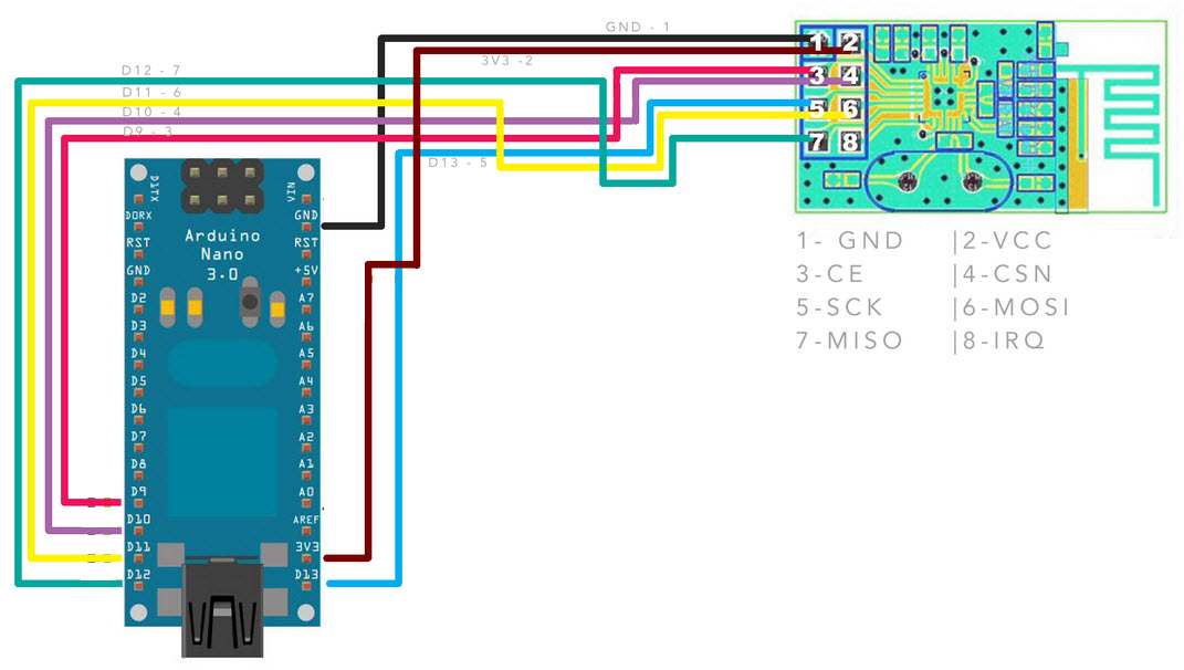
#define CE_PIN 9
#define CSN_PIN 10
const byte thisSlaveAddress[5] = {'R','x','A','A','A'};
RF24 radio(CE_PIN, CSN_PIN);
char dataReceived[10]; // this must match dataToSend in the TX
bool newData = false;
void setup() {
Serial.begin(9600);
printf_begin();
Serial.println("CheckConnection Starting");
Serial.println();
Serial.println("FIRST WITH THE DEFAULT ADDRESSES after power on");
Serial.println(" Note that RF24 does NOT reset when Arduino resets - only when power is removed");
Serial.println(" If the numbers are mostly 0x00 or 0xff it means that the Arduino is not");
Serial.println(" communicating with the nRF24");
Serial.println();
radio.begin();
radio.printDetails();
Serial.println();
Serial.println();
Serial.println("AND NOW WITH ADDRESS AAAxR 0x41 41 41 78 52 ON P1");
Serial.println(" and 250KBPS data rate");
Serial.println();
radio.openReadingPipe(1, thisSlaveAddress);
radio.setDataRate( RF24_250KBPS );
radio.printDetails();
Serial.println();
Serial.println();
}
void loop() {
}


connection on photo.
One nano 5V 16MHz works
The second nano with the Mini Pro 3.3V 8Mhz Bootloader writes 0x08 on serial monitor
Please don't post pictures of text - they are unreadable. Just copy and paste the text.
It looks like you are powering the nRF24 from the 3.3v pin on the Nano. I don't think a Nano can produce enough 3.3v current. Try powering the nRF24 separately (say from a pair of AA Alkaline cells) with the nRF24 GND connected to the Nano GND.
I note also that you have no 10µF capaacitor across Vcc and GND for the nRF24.
And your diagram does not show how the Nano is powered.
...R
Have you changed the resonator on the 3.7V Nano to an 8MHz one?
Thanks for your advice on inserting pictures.
I have connected the capacitor, but nrf behaves the same way.
Yes, resonator chenged on 8MHz.
Arduino working on 3.3V 8MHz. Not working NRF
Have you swapped the NRF modules over, or tried a different one to see if you get a different response?
For what it is worth I have (successfully) done exactly the same thing as you are trying to do. One important difference is that I as using one of these Nanos, which have a dedicated 3.3V regulator so that they can supply more current on the 3.3V pin. Most Nanos just rely on the 3.3V output of their USB-Serial chip, which often isn't enough to run the NRF24L01 modules.
Steps I've Made:
Replacing the controller from 5V to 3.3V
Disconnecting the 5V usb and connecting to the controller input.
CH340G power supply with 3.3V output.
Replacement resonator from 16MHz to 8MHz
Uploading Bootloader For Mini 8MHz 3.3V
All arduin power is now 3.3V. Arduino is working on my own, I successfully run the sketch blink. But NRF will only write 0x08 in the serial monitor. I tried 3 different NRFs on another nano with the same connection but (5v 16MHz) working normally.
Michal1989:
All arduin power is now 3.3V.
Where is the 3.3v power coming from?
How does the 3.3v power get to the nRF24?
...R
Michal1989:
Steps I've Made:
Replacing the controller from 5V to 3.3V
Disconnecting the 5V usb and connecting to the controller input.
Can you clarify what this means? When most people say 'controller' they would be talking about the microcontroller itself. But from looking at your photos and going by what you say here, I think you might mean that you have replaced the onboard 5V regulator with a 3.3V one. If that is the case, can you show us exactly what you've done and what model of regulator you've used?
Michal1989:
Replacement resonator from 16MHz to 8MHz
Have you used a resonator or a crystal? The photo isn't that great but it looks like you might have used a crystal without any load capacitors.
Michal1989:
I tried 3 different NRFs on another nano with the same connection but (5v 16MHz) working normally.
Just to be clear here- you have tried multiple different NRFs on both the 5V/16MHz and 3.3V/8MHz Nano. All of the modules work on the 5V/16MHz Nano but not on the 3.3V/8MHz Nano?
Solved. Under the microscope I noticed a small piece of tin connecting pin 10 and 11 directly to the processor. thank you all
Thanks for the update.
...R