I want to make a coin cell powered arduino(Wemos D1 mini actually) project.
The device has to power on by a button press, do something, then power down untill the button is pushed again.
I did some research and came across the following tutorial.
In this tutorial there are two options:
Supply power to the Wemos directly, after the action is complete, put the Wemos to deep sleep and use the (onboard) reset button to restart it.
Use a button to complete the circuit and provide power to the wemos. Downside is that you have the keep pressing the button till the action is complete.
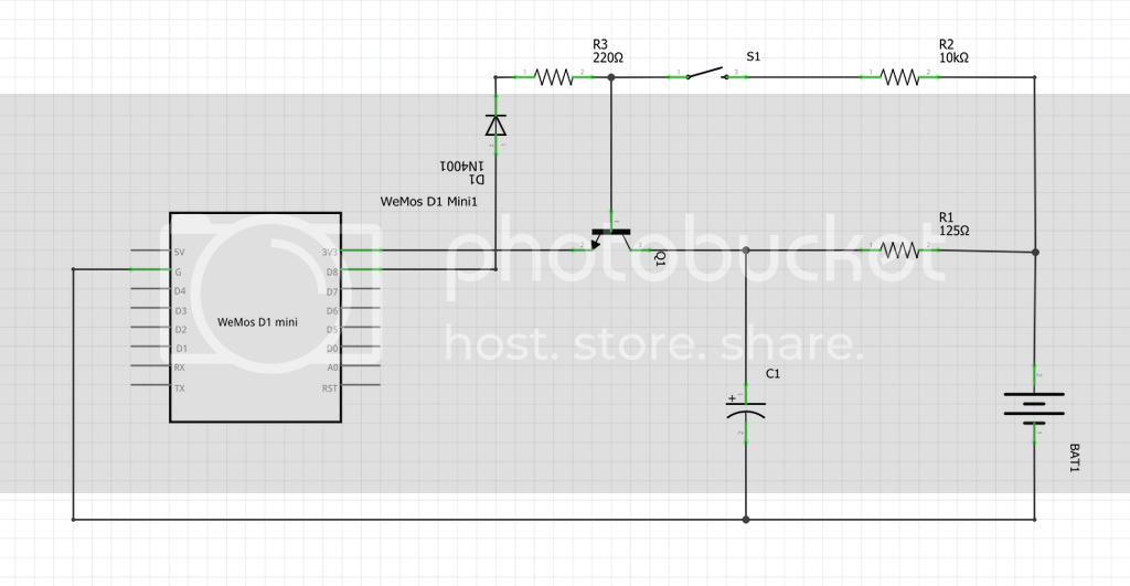
I was thinking off adding a third option. And I wonder if it is feasable. I have added a schematic.
pls don't mind the values of the components.
The battery will be a coin cell (3v), the capacitor is a 3.3F (The battery can not provide sufficient Amps to deal with the spike when connecting to wifi.)
I added a transistor. When the button is pushed the transistor enables the Wemos D1 to get power.
At the start of the Sketch, I set GPIO D8 to HIGH.
This will keep the transistor in the conducting state. You won't have to hold the button down anymore. Once the action is complete. Set GPIO D8 to LOW which will cut the power to the Wemos.
I think I will have to throw in an extra diode in series with R2 and calculate the right Resistor values.
Could something like this work?
(Or another question: Can I hook it up like this to see if it works? Or will I break something?)
Google recommends me to use a mosfet instead of a transistor to get a lower voltage drop.
Is my understanding correct that I should use a MOSFET with VGS(th) larger than the gatevoltage (in this case 3.3v (from the GPIO pin) minus the voltage drop of the diode?) So this will be 2.6v minimum.
And Rds ON will have to be as low as possible.
Would something like that work?
For example: VGS(th) = 1v
RDS ON = 1 Ohm (perhaps even smaller?)
The other thing is that when the power is removed before the shutdown is completed the outputs switch off. This messes up the turn off. One way round this is to use an RS flip flop to drive the FET.
So you expect the WeMOS to output a voltage 0.6 V higher than its supply voltage (even ignoring the diode which is spurious) in order to turn that transistor on? How do you expect it to do that?
The most practical approach is to use your option 1 or something similar, but rather than deep sleep, you use the Chip Enable pin with a push-button and a diode from an output pin (and a 100k pull-down resistor). On pressing the button, the chip starts up and turns the output on which keeps it operating until you choose to turn the output off.
And rather than fiddling with coin cells and supercapacitors, just use two AA (or AAA) alkalines.
The first thing to realize is that any kind of emitter-follower or source-follower circuit cannot be
efficient, and cannot be bootstrapped either (needs gain to bootstrap). In this circuit there are two diode
drops between the logic pin and the output of the circuit, so that the load would have to generate a voltage
about 1.4V higher than its supply to work this circuit.
The problem has no trivial solution, one transistor + passives will not do it.
One of the clean solutions is a CMOS RS-flipflop driving a p-FET or PNP switching transistor in
common-emitter (or common source) configuration. The CMOS logic takes only nanoamps
to power it so can be permanently powered up. (Two NAND or two NOR gates can be used to
fashion an RS fflop)
Two transistor circuits can be made to work - with just one you always find powering down the load
causes it to retrigger the circuit through the input protection diodes.