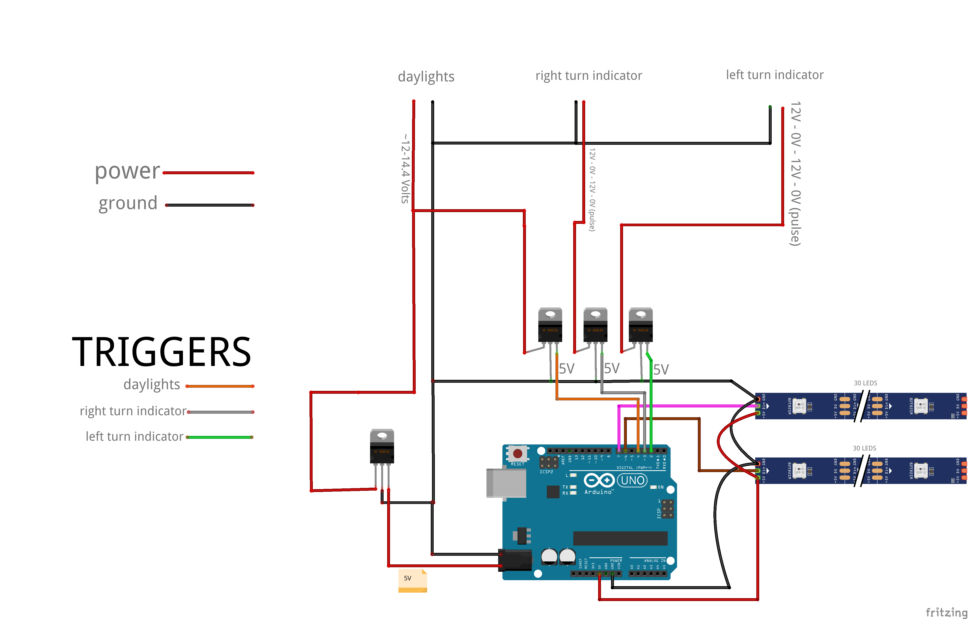
Hello, recently i tried to diy a project i found on youtube. i spend couple of hours to create the schematic so i can give all the information on what i am doing.
i am powering the arduino UNO via a dc jack in case you cant figure it out.
THIS is working PERFECTLY if i am powering the arduino via my laptop usb or connect the 5V Voltage Regulator directly to my scooter's battery.
My thought behind this is, that i would like the arduino to have power when the daylights are on = when scooter is running. so i would like to avoid having it attached to the battery directly. i googled a bit and saw that UNO has about 45mA. i couldnt measure my battery mA just volts so i cant figure out if it will drain the battery or not.
Plus its more convinient to power the arduino from the daylights; less cables to manage.
Recap.
The problem is that when arduino is powered by the DC jack, the led strips do weird stuff, blinking etc.. not working as indented.
But when i power it via USB (no regulator) or via the battery all works fine.
I have 0 experience with electronics/resistors/OHMS and that sort of other stuff. Any help to the right direction is welcome
Paul_KD7HB:
Not once did you tell us what voltage you are applying to the input power jack. Why is that?
Paul
Hi Paul, there is a note just right below the cable of the input power jack, its 5V via a voltage regulator. i read that UNO can do 6-20V, and safe margins are 7-12V as input. i already burned 2 boards for whatever reason and the dc jack input no longer works. so i am using a 5V power jack input on the new board.
mitsakos:
Hi Paul, there is a note just right below the cable of the input power jack, its 5V via a voltage regulator. i read that UNO can do 6-20V, and safe margins are 7-12V as input. i already burned 2 boards for whatever reason and the dc jack input no longer works. so i am using a 5V power jack input on the new board.
The Uno can run on 7-12 volts thru the power jack because it has an on-board 5 volt regulator to power the processor. If the DC power jack no longer operates, it's because the regulator has died.
If you connect your 5 volt power to the 5 volt pin of the Uno board, that will power the Uno directly, No regulator.
There is NO 5 volt power jack on any of my Arduino boards. There are 5 volt pins. Is that what you are using?
Using a voltage regulator to translate a signal from a higher voltage to 5V is not how to do it. These things were not designed to do that. You need to use a voltage divider or better still you need to use an opto isolator on each signal because automobile electrical environments are particularly noisy and tricky to use.
Why no series resistor or large capacitor across the LED strip?
You can not feed 5V into the barrel jack of an Arduino. You have a reverse polarity protection diode and a voltage regulator to get through. And the current the onboard regulator can supply is totally insufficient to drive 60 LEDs. You need 3.6 Amps to drive that many LEDs.
mitsakos:
i couldnt measure my battery mA just volts so
Measuring "battery mA" is a very bad idea. Except for very special cases it may damage battery, DMM or both and gives no valuable information.
You are right Arduino will drain the battery when powered all the time without proper usage of sleep. Connecting it to the light power supply is a good, simple solution.
Try to read more about power supplies in automotive. I have no experience but it is said there may be wild spikes of voltage (both high and low). You should protect the Arduino somehow. I would use at least a large cap to eat the transients. And a diode to protect the regulator from the large cap.
Grumpy_Mike:
And the current the onboard regulator can supply is totally insufficient to drive 60 LEDs. You need 3.6 Amps to drive that many LEDs.
The external 5volt regulator will also get in trouble with 3.6Amp and a 7-9volt drop.
That's about 8*3.6= 28.8watt.
Enough to release the magic smoke, even with a fist-sized heatsink.
Leo..
Paul_KD7HB:
The Uno can run on 7-12 volts thru the power jack because it has an on-board 5 volt regulator to power the processor. If the DC power jack no longer operates, it's because the regulator has died.
If you connect your 5 volt power to the 5 volt pin of the Uno board, that will power the Uno directly, No regulator.
There is NO 5 volt power jack on any of my Arduino boards. There are 5 volt pins. Is that what you are using?
Paul
I meant to say i use a 5V dc input which is voltage regulated by the LM7805, since that cable is 12V.
TomGeorge:
Hi,
This diagram may help, feel free to change, comment, criticize.
I will get a look at this as i dont understand any of the components you used. I will ask help from a local dealer. Thank you for your time.
The original issue is that when i am powering the ardunio from usb laptop, everything works fine. Also works if i power it from the battery of scooter via a 5V voltage revulator. But it WONT work if i do this from daylights cable.
I will get a look at this as i dont understand any of the components you used.
These were all the components you used in the original diagram, plus resistors and capacitors that you should have used.
But it WONT work if i do this from daylights cable.
What are "daylights cable"?
The L7805 will not be able to supply enough current to light all those LEDs at full brightness, so when you say:-
when i am powering the ardunio from usb laptop, everything works fine.
You are not testing them correctly as there is no way you can get that much current from a USB socket. The maximum from a USB socket is 500mA. You will have to keep the brightness down or not light all the LEDs at the same time to stand any chance of working.
Grumpy_Mike:
These were all the components you used in the original diagram, plus resistors and capacitors that you should have used.
What are "daylights cable"?
The L7805 will not be able to supply enough current to light all those LEDs at full brightness, so when you say:-You are not testing them correctly as there is no way you can get that much current from a USB socket. The maximum from a USB socket is 500mA. You will have to keep the brightness down or not light all the LEDs at the same time to stand any chance of working.
its a usb3.0 port with SS letters on it(superspeed). i have tested over 5 times and with USB it works as it should. the brightness on all 60 leds is 250 plus the animation, and i had no issue with it.
"Daylights cable" is the cable that i get the power source to power up the arduino. since its daylights that cable always has voltage, when scooter is running. so i thought a good way to power up the arduino.
What you describe as the "DC jack" is essentially useless! Do not use it - or the "Vin" pin - for any purpose!
It is essentially an ornament provided in the very beginning of the Arduino project when "9V" power packs were common and this was a practical way to power a lone Arduino board for initial demonstration purposes. And even then it was limited because an unloaded 9 V transformer-rectifier-capacitor supply would generally provide over 12 V which the on-board regulator simply could barely handle.
If powering from batteries, as long as the battery pack cannot exceed 5.5 V, this must be connected to the 5 V pin.
Nowadays, 5 V regulated switchmode packs are arguably the most readily available in the form of "Phone chargers" and switchmode "buck" regulators are cheap on eBay so these can be fed into the USB connector or 5 V pin to provide adequate power for most applications. Unfortunately, many tutorials or "instructables" are seriously outdated or misleading and have not been updated to reflect the contemporary situation.
mitsakos:
its a usb3.0 port with SS letters on it(superspeed). i have tested over 5 times and with USB it works as it should. the brightness on all 60 leds is 250 plus the animation, and i had no issue with it.
Well for USB 3 the current is increased but in no way matches what you need, so even though you think you have no issue you have. Have you measured voltages or looked at waveforms? Very odd things could be happening that will bite you later, not all electronic abuse shows itself by failing immediate, it could take weeks months or even a year before you get a loss of function.
In the USB 1.0 and 2.0 specs, a standard downstream port is capable of delivering up to 500mA (0.5A); with USB 3.0, it moves up to 900mA (0.9A).
"Daylights cable" is the cable that i get the power source to power up the arduino. since its daylights that cable always has voltage, when scooter is running. so i thought a good way to power up the arduino.
So this is a wire on your scooter that has permanent power on it?
Grumpy_Mike:
Well for USB 3 the current is increased but in no way matches what you need, so even though you think you have no issue you have. Have you measured voltages or looked at waveforms? Very odd things could be happening that will bite you later, not all electronic abuse shows itself by failing immediate, it could take weeks months or even a year before you get a loss of function.
So this is a wire on your scooter that has permanent power on it?
as stated i know "nothing" like John Snow so i havent measured voltaged or wavesforms. have no knowledge to do so. i only measured the volts of the power cables i am modifying.
Yes!. "daylights" wire has permanent power when the scooter is running. (~12V)
Smajdalf:
Did you measure the voltage on the daylights cable? With connected Arduino? What is voltage between 5V and GND pins of Arduino?
There is no reason to have "daylights" trigger when Arduino is powered from the daylights. It will be HIGH as long as Arduino is powered.
the voltage on daylights cable is ~12V bit higher when scooter is running. then i use a voltage regulator too drop it 5V so i can supply it to the DC jack. from what i read that is wrong. i will try to power the arduino from the 5V pin.
as stated i know "nothing" like John Snow so i havent measured voltaged or wavesforms
Yes I know that is why I am telling you that when you say "it works" you are deluding yourself and it actually doesn't. It might appere to function but it is not right and will go wrong eventually.