Walkie-talkies to control DSLR camera via Arduino

I want to remotely control my Canon 340D DSLR. It has a socket for a remote control unit. Such a unit is essentially two switches -- one switch closes the circuit to the auto focus mechanism, the other closes the circuit to the shutter release. No power source in the device itself. The photographer has to be at the camera as it is connected to the camera by a short cable..

I want to operate the camera from a distance for bird photography. I could use bluetooth but its range is about 10 m I believe. This would be fine for many situations. A greater range of say 50 to 100 meters would open up interesting possibilities.

I have hand held two way radios (GSE brand, model TX675, 2W power). Good quality with a range of over 1000 m in good conditions. I'm wondering how I could use these to control the camera.

They don't have any digital output as far as I can tell, only audio. How can an audio output trigger a digital response in an Arduino? I won't open the radio to work on it internally. It does have an earpiece socket. Could the earpiece cable provide useable voltage signals?

The audio signals I can transmit are:
. squelch -- a short "blip" for a fraction of a second
. page -- high pitched multi-tone, about 5 seconds duration
. voice

I've found guidance on using Arduino to control the camera via reed relays and optocouplers, but they don't consider radio in place of cable.

Any thoughts? How to convert an received audio signal to a digital one,ie, hi/low?

John.

There are many Arduino-compatible radio modules with range exceeding 100 m. Even the $1 433 MHz modules can do that, if you use a good antenna. The arrangement I use below gives 300 m line of sight range. Use the VirtualWire library for reliable communications.

The balanced dipole is 33 cm from tip to tip.

It looks like the FC-04 sound sensor board will convert sound to a digital signal.

Would it be possible to connect the earpiece wires directly to the Arduino & have the sketch read the voltage to determine the presence of an audio signal?

have the sketch read the voltage to determine the presence of an audio signal?

Detect signal versus no signal, yes.

Define "audio signal".

I'm checking out the 433MHz devices. Ta.

When I send a page signal, both radios emit a 5 second multi tone sound. That's the audio signal. I think the FC-04 sound board could be used to detect that and produce a digital hi (or low) on its output pin.

I don't really want the sound, it's better to be quiet. Although if I'm using an earpiece it would be quiet.

If I cut off the earpiece, would the wire provide a voltage signal (when the page is sent) that could be used by the Arduino directly? Would I use an analog or digital pin?

John.

An earphone signal would be AC, and would damage any Arduino input, as inputs cannot accept negative voltages.

You will need to convert the signal to DC and possibly amplify it, or offset the AC by biasing the input. Google "arduino audio signal" for tutorials.

Reliably detecting tones is very difficult, so you are much better off with a digital, Arduino compatible radio.

Thanks. Sounds like it would be simpler to use the FC-04 to do the work. It would act as an "audio coupler" and protect both radio and Arduino.

Forget the walkie talkie. You’re thinking good but for the money you’re going to spend hacking that to work you could buy an actual digital packet radio that would do the job out of the box and have cash left over for a new lens.

Some of the LoRa radios get miles of range if you’ve got decent line of sight.

I built such a walkie talkie audio circuit to open a door remotely, and will attach the schematic in case you want to do it the hard way. It's basically an LM358 dual op amp, with one op am rigged to amplify and rectify the audio signal from the walkie talkie audio jack and gradually charge a capacitor, and the other rigged as a comparator which triggers the Arduino, which in turn drives a servo.

But I think your camera situation is much simpler than that, and doesn't really require an Arduino at all. If your camera is like my 550D, the focus trigger and shutter trigger do not have to be engaged sequentially. If you engage both triggers at the same time, the camera will focus first, then immediately take the picture. So you really just need one trigger.

A simple, cheap remote control set could be used to trigger the camera directly, with no need for audio to digital conversion. These remotes use the PT2262 and PT2272 chips, and come in transmitter/receiver sets for under $4 plus the cost of a 23A battery (used in a variety of garage door openers). Here's a typical source for the 315 MHz version (also comes in 433 MHz).

And I'll link below to a video on these remotes. What you would need is the "M" momentary receiver chip. The guy in the video completely misunderstands the unsoldered pins. They are used to set a security code that's the same on both transmitter and receiver so other transmitters will be ignored. The pins are left unsoldered in case you want to tie any of them to 5V or ground to create a unique code.

The 315 MHz receiver would require an antenna wire to be added, presumably 8.9 inches long, which is 1/4 wave length. The transmitter has a telescoping antenna, but it is considerably shorter than that - for reasons I don't understand.

If you press the A button on the transmitter, the A pin on the receiver will go high. Since the camera requires the triggers to be grounded, you would need to add a cheap NPN transistor such as a 2N3904, the base of which is driven by the A pin through a resistor. The collector would be connected to the camera triggers, and the emitter to ground.

You would also need a power supply for the receiver. A 9V battery would probably work fine.

The big question of course is range. The specs say up to 100 meters, but that's not realistic. The end of the video shows 100 ft is likely, and that's without any antenna tuning. It's possible that playing with both the transmitter and receiver antennas could give you significantly more range. I won't pretend to understand antennas, but there are people here who do, and they would probably help you optimize the antennas.

Given the low cost of this option, and the simplicity gained by using it, I think it's worth giving it a try. Be sure you get the right cable for your camera's remote trigger port. Mine takes a 2.5mm stereo audio plug, but older models may be different.

Thankyou, everybody. Much food for thought.

J.

ShermanP,

I looked at that "garage door opener" device. Do you know how the 12V is involved? Where is the 12 volts?

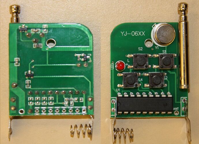
Well, I meant that the battery that supplies the 12V is the same one that's used in many older door opener clickers. It's the A23, sometimes called the 23A, which is about the diameter of a AA, but shorter. It's an alkaline 12V battery that fits inside the transmitter case. The transmitter only draws current when you press a button, so the battery should last a while. In the attached picture of the inside of the transmitter, you'll see at the bottom a place for the battery, with the typical spring on the negative end. You might be able to find the battery locally, but if not you can order them from Amazon or Ebay.

The receiver is a different matter because it has to be ON all the time listening for a transmission. I think the traditional 9V battery would be a good choice, but don't really know how long it would last.

Since I have the 315 MHz remote set, I decided to see if it would trigger my 550D, and it does.

First I need to correct something I said earlier. It turns out you do not have to trigger the autofocus contact at all. You just trigger the shutter release contact, and so long as you hold the button down long enough, it will autofocus, then take the picture.

So the attached picture is my trial setup. On the left is the power supply barrel connector for the receiver, and I used 5V because the specs on the Ebay pages say it's 5V. But the PT2272 and the dual op amp datasheets all say a higher voltage will work, so when I test range tonight, I'll also test using a 9V battery, which is what you would want to use, and which might even give you more range.

Also trailing off to the left is the red antenna wire, which is about 9 inches long, sticking straight up. I have no idea if this is optimum. Then at the bottom is the transmitter with the antenna extended.

The black object at the top is just a manual shutter release that I've taken apart and connected alligator clips to the innards to bring out the shutter release contact and ground. This is the only device I have with the right plug for my Canon remote socket. But of course your final version would just directly wire the cable leads into the circuit.

Then as you can see on the receiver module I connect power and ground, and the Vt pin, which goes high when ANY button is pressed, is connected through a 10K resistor to the base of a 2N4401 NPN transistor. The collector goes to the shutter release contact, and the emitter goes to ground.

So when a button is pressed, Vt goes high, which turns on the transistor, which grounds the shutter release connector, which makes the camera focus and take a picture.

Range remains the big question. If I have time tonight, I'll try to test that.

Anyway, this definitely does work, and doesn't require any walkie talkies, any audio-to-digital conversion, or an Arduino. And the total cost is just a few dollars.

Film at 11:00.

Thanks for all that. I've watched the video. Do you know how I can tell if the unit will be momentary action or latched, based on the info provided by the seller on ebay? I want momentary.

I have not come across 12V batteries of that size.

I think this is worth getting. The effective range is important but 100 feet is adequate for many situations. I think I will also pursue the walkie talkie and audio coupler path cos the concepts interest me and the range will cover every situation. Also keeps the topic an Arduino topic.

Thanks again. Hope you're finding this of interest. My camera works similarly to yours.

J.

Does the transistor act like a relay? Just a switch to close the camera circuit?

Yes, the transistor is turned on (low impedance path from collector to emitter) when current flows from the base through the emitter. A little base current enables a lot of collector current. So in this application it is essentially equivalent to a relay or switch. When turned on by the receiver, the transistor simply shorts the shutter trigger contact to ground, just as a remote cable release would do.

I don't know where you are, but if the A23 battery isn't available locally, you can order them online. No matter what you use for this task, you will also need a cable with the right connector to plug into the camera. On Ebay you can search for cable release canon 350D, and you will see some very cheap ones. Or I think any 2.5 mm stereo audio cable would also work. I saw one for $.99 that has 2.5 mm male at one end, and 3.5 mm male at the other. You could wire a 3.5 mm female jack into your circuit, which would make the cable detachable.

Unless the Ebay listing says "momentary", the only way to tell is to zoom in on the picture and try to read the part number on the receiver chip. In the listing I linked to before, you can (just barely) see that it says PT2272-M4. If it's latching, the M will be an L. I think the great majority of these remotes on Ebay are momentary.

My distance test was rained out, but I'll do it today if possible.

The idea of a sound trigger with better sensitivity than the "clap sensors" and some reasonable noise immunity touched on some ideas I've been working on, so I put together a little audio signal processing sketch. The code below triggers (the built in LED) upon receiving a 1 kHz tone. It seems robust against tones outside of that (excepting image frequencies) and noise in the environment in the sense that there weren't noticable false triggers.

I tested using an Android phone app as the tone source. In a quiet room it rejects tones more than about 5 Hz off center. Outdoors, range from the tone source was limited, presumably because of greater background noise.

The approach is to compute the running average signal power through a narrow band pass filter at 1 kHz center and compare that with the running average of the total signal power. The LED is turned on when the 1 kHz power exceeds half the total signal power.

/* Sketch implements single tone detection using a narrow bandpass filter
 *  Tone detection occurs when integrated power out of BPF is greater than
 *  one half the integrated power of the full ADC band
 */

// ***************************************************************************
/* Integrator class maintains running average of input using recursion formula
    xAvg = x + xAvg - xAvg/(2**N) where N is a positive integer
    Effective integration period is on the order of 2**N
*/
class Integrator {
  public:
    long int xAvg ;       // Running average left shifted N bits
    int shift ;

    Integrator(int N) {   // Constructor for class
      xAvg = 0 ;
      shift = N ;
    }

    // Update average with sample and return updated average
    long int integrate(long int xIn) {
      xAvg = xAvg + xIn - (xAvg >> shift) ;
      return (xAvg >> shift) ;
    }
} ;

// ***************************************************************************
/* Digital bandpass filter for sample rate 2500 Hz, passband 995-1005 Hz */
/* Using: https://www-users.cs.york.ac.uk/~fisher/mkfilter/trad.html */
/* Digital filter designed by mkfilter/mkshape/gencode   A.J. Fisher
   Command line: /www/usr/fisher/helpers/mkfilter -Bu -Bp -o 1 -a 3.9800000000e-01 4.0200000000e-01 -l */

#define NZEROS 2
#define NPOLES 2
#define GAIN   8.057026980e+01
static float xv[NZEROS + 1], yv[NPOLES + 1];
static int filterloop(int xIn) {
  xv[0] = xv[1]; xv[1] = xv[2] ;
  xv[2] = xIn * (1 / GAIN) ;
  yv[0] = yv[1]; yv[1] = yv[2] ;
  yv[2] =   (xv[2] - xv[0]) + ( -0.9751778762 * yv[0]) + ( -1.5980786463 * yv[1]);
  return int(yv[2]) ;
}

// ***************************************************************************
// Parameter and object definitions
#define sampleIntervalMicros 400 // Sample interval in microseconds
long int nextInterval ;         // Time of next ADC collection cycle
Integrator adcRunningMean(8) ;  // Integrator object to track ADC offset
Integrator channelPower(6) ;    // Integrator object to track full band channel power
Integrator tonePower(6) ;       // Integrator object to track filter band power

void setup() {
  digitalWrite(LED_BUILTIN, LOW) ;
  pinMode(LED_BUILTIN, OUTPUT) ;
  Serial.begin(115200) ;
  nextInterval = micros() + sampleIntervalMicros ;
}

void loop() {
  if (micros() >= nextInterval) {
    int x = analogRead(A0) ;
    long int adcMean = adcRunningMean.integrate(x) ;
    long int y = filterloop(x) ;

    long int chanPower = channelPower.integrate(sq((x - adcMean))) ;
    long int sigPower = tonePower.integrate(sq(y)) ;
    nextInterval += sampleIntervalMicros ;

    if (2 * sigPower > chanPower) {
      digitalWrite(LED_BUILTIN, HIGH) ;
    } else {
      digitalWrite(LED_BUILTIN, LOW) ;
    }
  }
}

The bandpass filter was designed using the tools at https://www-users.cs.york.ac.uk/~fisher/mkfilter/trad.html with the parameters Filter Type Butterworth/Bandpass, Filter Order 1, Sample Rate 2500 Hz, Corner Frequencies (950, 1005). The tool produces C code which is used essentially verbatim.

The integrator class defines a simple no multiply low pass filter that is used to average the DC offset of the ADC, to average the power out of the 1 kHz BPF, and to average the power out of the ADC.

The sketch was run on an Uno with a max9814 microphone board configured for 60 dB gain on input A0. I initially used a FC-109/max9812 20 dB gain board which was insufficiently sensitive for reliable operation.

The ADC sampling rate must be uniform and consistent with the band pass filter design of 2.5 kHz sampling. Sampling rate is controlled by using a "BlinkWithoutDelay" sort of structure to sample at a 400 microsecond interval. The signal processing bit as written is sufficiently fast to keep up with a 350 microsecond sample interval, but not much more.

The sketch serves as a neat demo of image frequencies as it will trigger the LED at any frequency (n2500 + 1000) or (n2500 - 1000) kHz where n = (0, 1, 2, 3, ...).

I'm not sure how practical any of this is for the original poster's problem, but I got the chance to work through some ideas and it may be of use to someone.

Mark,

That's interesting. There is a method of bird identification by audio analysis of their calls/song.That would probably interest you. I feel this approach is too sophisticated for my needs.

ShermanP (Potter?), I can source the 12V batteries. My camera has a 2.5 mm socket so I'm using a stereo plug to drive the camera. I think that part will be easy. I will want it to focus and shoot in response to a single signal.

I've ordered the RC devices - 1x 315Hz, 1x 433Hz, and the audio sensor board. I'll develop both methods.

J.

I've realised that an earlier project I made suits the task of camera remote control.

I made a device that sounds an alert when my phone receives an SMS. I needed this cos in some circumstances I don't hear the phone's SMS alert.

I used a Bluetooth connected to a Nano connected to a buzzer. I built an Android app. When the phone receives an SMS the app sends a code to the Bluetooth & the Nano sounds the buzzer. I included a button to cancel the buzzer and send an acknowledge SMS back to the caller.

I only need to substitute the camera for the buzzer. Has the advantages of unlimited range & the ability to ack the command take a photo. Disadvantage is I need to use two phones.

So now I will be developing three different techniques.

John.

No, it's Sherman Peabody. I am Mr. Peabody's boy Sherman.

Well, John, I would say that devoting two phones to this is like having an unlimited budget, even moreso than two walkie talkies.

I note that Ebay sells cheap pre-formed 315MHz and 433MHz helical antennas, which presumably would be right for the remote receivers. I say presumably because you never know with antennas.

I think the opamp circuit I posted earlier would drive the camera from a walkie talkie's audio jack without the need for an Arduino. You would need to reverse the polarity of the final output, which I think could be done by reversing the final opamp inputs, and add a diode, and then I think it would need a little positive feedback in that stage to convert it to a schmitt trigger. I'll attach a picture of the final breadboard version in case you or anyone else ever wants to try it. The audio part is the 8-pin DIP chip on the left and associated parts. The stuff on the right is the Arduino, BLE and power supply, none of which you would need. You would just need a 9V battery.