Need advice on opto-transistor switch

I need some help in understanding the interaction between an opto coupler and PNP transistor.

I am designing a DCC accessory decoder. Currently all is working fine on the breadboard using an Atmega 328P. I now need to implement the ACK signal to the DCC buss. The spec calls for an increase of at least 60mA for 6ms in the DCC buss current.

There are some examples how to do this on the OpenDCC site. The 6ms ACK signal drives an opto-coupler which in turn switches a PNP transistor, to handle the required current, connecting a resister across the DCC buss.

The relevant part of the circuit looks as follows (the top section):

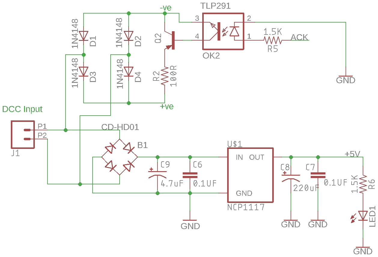
The original Opto is a PC817 and the transistor a BC860. I cannot easily source those locally so am replacing them with a Toshiba TLP291 and a MMBTA56L transistor. Both are very close to the originals.

My concern is the way the opto is coupled to the transistor. I can understand the transistor turning on when the opto turns on but what controls the base-emitter current? Also when the opto turns off the transistor base basically floats - how does that turn the transistor off (no base current? - that sounds a bit shaky to me)? My understanding is that the base needs to be switched to less than 0.7 lower than the emitter to turn it off.

I am reasonable when it comes to digital circuits and programming micros, but useless at analogue designs. Will the above circuit work as is?

Any advice will be appreciated.

Willem.

[EDIT - I'm not happy with my answers]
Hello Willem,
To answer as best I can:

I can understand the transistor turning on when the opto turns on but what controls the base-emitter current?

The base-emitter current flows through the 100 ohm resistor R2, so maximum available current is what can flow through that resistor. However, as that current is also the collector current, the base current will be the total current through the resistor / gain of the transistor.

Also when the opto turns off the transistor base basically floats - how does that turn the transistor off (no base current? - that sounds a bit shaky to me)? My understanding is that the base needs to be switched to less than 0.7 lower than the emitter to turn it off.

I suspect you are confused with MOSFETs, which are voltage controlled, and must have a definite voltage on their gate, not left floating. Transistors are current controlled, disconnect the base and they get no base current, so they turn off. It might be helpful to have a 10k to 100k resistor from the base to the +ve side of R2, but I don't think it's essential.

Will the above circuit work as is?

I think probably yes. Try it and see.

@PerryBebbington

Thanks for the reply. I should have mentioned that the DCC signal is basically 12 - 15V, so that is what we will have between +ve and -ve. Yes you are right, we will only have about 0.6 - 0.7 (relative to base and collector) at the emitter. So current might be low.

I realize we need base current to turn it on. My concern is that in most circuits it is bad practice to leave anything floating. A 100K from base to +ve might be a good idea.

I realize best will be to test it. Problem is we are talking SMD components - not so easy to put together a test circuit. I need to see how to do this (very careful soldering?).

Again, thanks.

Willem

[EDIT: Thanks for the update.]
Spec sheet says DC gain is about, or a bit higher, that 100. 100 Ohm at 12 Volt says about 120mA (which is what I would like). So base current should be around 1.2mA which should be safe. Might just work as is - I will however test before I committing to a final PC board design.

BJTs don't float, that's a property of MOSFET gates which are isolated by a layer of silicon dioxide.

BJTs do have leakage currents though, and these rise rapidly with temperature (though usually sub-nanoamp).

Sometimes such a base-emitter resistor is used to prevent collector-base leakage currents being amplified
by the transistor. Here I think its a non-issue, the leakage really is small and the circuit impedance is 100 ohms.

@MarkT

Thanks for the reply.

It seems that it should work just fine. I will, however, breadboard check before doing the final board layout.

Willem.

You do not need the negative side diodes in the "ACK" circuit. Just use the same negative rail for both.

@Paul__B

Call me dumb, but I am not with you on this.

The DCC signal is what they like to call a bipolar square wave. The phase switches between 5 to 8KHz. I need to draw ~100mA during both halves of the cycle, hence the full wave bridge.

If I am missing something I would really like to know.

Willem.

You have two rectifier bridges doing the same job. You do not need two. You could connect your current dump circuit across the bridge marked "CD-HD01" that has the regulator but the reservoir capacitors would interfere with its operation. So you need to derive the positive voltage from a second pair of diodes replicating the "top part" of that bridge but use the "bottom part" as it is by using that as the negative connection for your current dump.

Ah, thanks. I now understand what you are talking about.

I need to look into that.

Willem.

Bipolar what volage ?

What are the positive and negative rail voltages ?

The DCC signal is derived using an H-Bridge as used to drive a DC motor. The supply voltage is anything from 12 to 18 volts (I run N-Gauge with a max of 15V - usually 12V).

The H-Bridge output is switched between "forward" and "reverse" to provide a continuous stream of 0's and 1's - 116us period for a 1 and 200us for a 0. So those rails will have, in my case, max 15V across them.

Hope that answers the question.

Willem.

You're using a purely DC signal 0 to 18V) for the AC input of the full wave bridge ?

Willem43:
Ah, thanks. I now understand what you are talking about.

I need to look into that.

It's just a simplification - but a quite useful one.

In fact, if the power supply in the bottom half is feeding the intelligence controlling the current shunt, you do not need the opto-coupler at all, just an NPN transistor or (much better) logic level FET and the 100 Ohm resistor. :grinning: (And those two diodes.)

@raschemmel

You're using a purely DC signal 0 to 18V) for the AC input of the full wave bridge ?

I don't understand why you think I have 12V DC input to the bridge rectifier, unless I misunderstood what you meant by you asking "What are the positive and negative rail voltages?". If by "rail" you mean the actual train track, that does not have DC, it gets the DCC "bipolar square wave" generated by the H-Bridge (as explained in post #10 above). The 12 volts DC goes to the H-Bridge.

I thought you asked what the voltage is between +ve and -ve in the original schematic.

So, no DC to the bridge rectifier, just the DCC signal which looks like this (the signal driving the H-Bridge):

Willem.

I thought you asked what the voltage is between +ve and -ve in the original schematic.

Yes I was and I'm not sure you answered my question.
You showed me a waveform with tells me nothing about the voltage. I see no voltage on that waveform.

Let's try a different approach. Are you telling me that you are calling the signal "bipolar" because it changes from high to low ? Do you know what "bipolar voltage " means in electronics ? It means there are two RAILS (YES RAILS) That's what engineers and technicians call the POSITIVE maximum (positive rail) and
the negative minimum (most negative voltage) Just to be clear. In electronics, negative means less than zero. I don't see anything indicating there are any NEGATIVE voltages on your train system. If there are
please indicate where and what those voltages are . When I ask what are the positive and negative RAIL voltages I am asking is it +/- 12V (-12V to +12V) ? In which case the +/- rails would be -12V and +12V.
So again I ask.
Do you , or do you not have any negative voltage ? Is the DCC signal feeding the full wave bridge in fact
zero volts to +12V ?
OR
is it -12V to +12V ?

Let's look at the clues:

  1. DCC inputs, P1 & P2, feed a bridge rectifier before
    the regulator.
  2. The DCC lines P1 & P2 are driven by an
    H-bridge.
    Therefore, P1 & P2 do reverse polarity.
    Right?

Let's look at the clues:

You can see the waveform.
Read the OP's explanation:

The DCC signal is derived using an H-Bridge as used to drive a DC motor. The supply voltage is anything from 12 to 18 volts (I run N-Gauge with a max of 15V - usually 12V).

The H-Bridge output is switched between "forward" and "reverse" to provide a continuous stream of 0's and 1's - 116us period for a 1 and 200us for a 0. So those rails will have, in my case, max 15V across them.

Now tell me how either the forward or reverse dc voltage that drives the train can feed the AC input of
a bridge rectifier ?
AC stands for ALTERNATING CURRENT.
Is the forward or reverse 12V dc voltage AC (Y/N) ?
Will a DC voltage work as an AC input to a bridge rectifier (Y/N) ?
Is the OP going to drive the train forward one inch and then reverse it one inch and repeat that to generate an AC voltage ?
How EXACTLY is that going to work ?
Enlighten me.

@raschemmel
Let me try again. I honestly do not quite know how to explain this but I am going to try.

Firstly, the above waveform is a 5V signal straight out of the ATTiny85 running the DCC++ generating code, adapted to run on the ATTiny85 (by me). Please note that the 1's are 116usec and the 0's 200usec. The displayed wave represents an idle "packet".

Next, I am not an electrical/electronic engineer, I am a software programmer (at least used to be - retired now), but love to tinker with electronics and having great fun programming micro controllers. I also need it for my model railway layout.

So, forget me calling it a bipolar signal (I was quoting from the DCC++ forum). I have created a simple diagram representing an H-Bridge.


Referencing the above diagram:
I apply 12V between VCC and GND.

Next the above DCC waveform is applied to IN1 and an inverted copy is applied to IN2.

When IN1 goes high Q2 turns on, IN2 simultaneously goes low and Q3 turns on. So B becomes VCC and A becomes GND.

Half way through the period IN1 goes Low and IN2 high. Q1 and Q4 now turns on and A becomes VCC and B GND. (This happens at ~8.6KHz for 1's and 5KHz for 0's).

A and B are connected to P1 and P2 in the original schematic. As far as my understanding goes that will produce 12V across +ve and -ve.

If you can tell me what that type of waveform is called I can make sure I use the correct terminology in future posts.

I hope that clears up the confusion.

Willem.

EDIT:
While preparing this post, I am rather slow, two more posts appeared. Let me give some explanation.

A-B in this post is what is also applied to the train track (the Load). It is not DC. The model loco has a decoder on board interpreting its address and instructions as to speed and direction (among other things). Power is derived using a similar bridge circuit. The decoder applies power to the the DC motor, phase according to direction and PWM is used to control the speed.

Allowing mobile decoders to be individually addressed allows more than one loco to share the same track at the same time and being individually controlled. Believe me, it was quite a shock coming back from modeling using DC in the 70's and finding it became DCC (By the way, that stands for Digital Command Control).

@willem43,
I know what an H-bridge is and how it works.
Your last post doesn't answer any of these questions :

Now tell me how either the forward or reverse dc voltage that drives the train can feed the AC input of
a bridge rectifier ?
AC stands for ALTERNATING CURRENT.
Is the forward or reverse 12V dc voltage AC (Y/N) ?
Will a DC voltage work as an AC input to a bridge rectifier (Y/N) ?
Is the OP going to drive the train forward one inch and then reverse it one inch and repeat that to generate an AC voltage ?
How EXACTLY is that going to work ?
Enlighten me.

A-B in this post is what is also applied to the train track. It is not DC. The model loco has a decoder on board interpreting its address and instructions as to speed and direction (among other things). Power is derived using a similar bridge circuit. The decoder applies power to the the DC motor, phase according to direction and PWM is used to control the speed.

Unless the train runs on batteries, the A-B voltage is pwm dc which, by definition contains power.
The voltage that goes to the train motor comes from the track so don't tell me it's not power.
I don't know what you mean by "a similar bridge circuit".

This is getting difficult - I get the feeling we are talking past each other.

Yes, I assumed you know exactly what an H-Bridge is and how it works. I used the figure to try and explain where I apply my DC 12 Volts and also how the DCC signal is derived, where it is applied and what it looks like.

The A-B, from above, 5 - 8KHz AC square wave (lets call it that for lack of a better name) is what sits on the tracks. The AC square wave on the tracks is kept going at all times - hence the need for an idle "packet". The loco motor is isolated from the track and is driven by a tiny decoder on-board the loco. The decoder rectifies the AC square wave from the tracks to get the DC to drive the motor (instead of batteries). The tracks never carry DC.

Apart from the idle "packet", the 1's and 0's in the above waveform are encoded to represent an address and instructions as to how to control the loco motor. The decoder then applies the DC to the motor in either forward or reverse at a speed as instructed.

Now your questions:

  • Now tell me how either the forward or reverse dc voltage that drives the train can feed the AC input of a bridge rectifier ?
    The DC voltage used to drive the loco forward or in reverse only exists inside the loco - after the decoder rectified the track AC square wave. The track 5-8KHz AC square wave is perfectly capable to drive a bridge rectifier.
  • AC stands for ALTERNATING CURRENT.
    Correct.
  • Is the forward or reverse 12V dc voltage AC (Y/N) ?
    There is no forward or reverse DC voltage on the track, it is only AC (square wave).
  • Will a DC voltage work as an AC input to a bridge rectifier (Y/N) ?
    Not as an AC input of course. It will however provide the required current through the relevant diodes - however, does not apply here.
  • Is the OP going to drive the train forward one inch and then reverse it one inch and repeat that to generate an AC voltage ?
    Since no DC is used on the track to determine direction, and an AC square at 5-8KHz is always present, the AC is already there.
  • How EXACTLY is that going to work ?
    I tried to explain that above.
  • Enlighten me.
    Hope that helps. Ask if you need a better explanation - I can only try.

Willem