Hello,
I have 300 addressable LEDs in total on 3 strings of 100 all connected together with the data cable from an ESP8266. I have power running to each string from a power supply and that is running fine. I have tried several examples from the FASTLED library, but the lights work up until the same spot, which is at about 225 LEDs of the 300. I have the data line from the ESP connected to the first string, that is then connected from that string to the next and so on. How do I boost the signal or what else is required to get past this issue?
Forgot to mention that the LEDs are on a custom ordered build with 10 inches between them making it 300 x 10” = 3000” or 250’ feet in total length.
As the data signal is regenerated by each LED, it is nothing to do with the single going it. It is a faulty LED either the last one that lights up or the first one that doesn’t light up. It need replacing.
Thanks both! Unfortunately I cannot post a video here so you can see the behaviour. It is weird how the lights react.
Each time I turn on the lights the sequence, patterns, etc. run like expected until about 25% of the third string. Then it slows down and turns on more lights over time, but never ending at the same light and never going more then 35% of that string (Sometimes even one at a time for the last few).
Also, where the first two string LEDs and a few on the third string are flickering and dancing, the last bit is slow to change or stays solid colours.
I can only think that there is some data transfer degrade across the line...
I have checked all the LED connectors
Tested each line individually
Added a replacement 3rd string which results in the same behaviour
Seems that all LEDs are working fine however, the data is not reaching the last bit. Sorry for this puzzler...
Added a photo of my climbing wall for context of what I am working with... Lighting up holds from behind the wall, but testing out that they all work.
Next step is to try replacing the ESP8266 with an Adafruit Metro, then an Arduino Mega 2560 and see what results are.
Ok so not quite the fault you were originally describing.
I can only think that there is some data transfer degrade across the line.
As I said before the data signal gets regenerated at each LED, so if it fails mid strip it is nothing to do with the data signal.
What you did not describe is how you wired things up and what the power supply is and how you wired the power and ground to each strip. Do you have a large capacitor on the strip, does each LED on the strip have a small surface mount capacitor fitted?
First what happens when a single on LED is sent along the length of the strip? Does this work consistently?
First let me apologize for taking so long to reply. Things have been a bit crazy and I have not been able to spend too much time on this issue. I do have a great update though, but to answer your question I will try to describe what my current wiring is and what I did that helped me move forward.
I had a resistor on my data line but I added a single 1000uF capacitor (only received my kit a couple weeks ago) that is now between the power supply and the LED strings positive lines from either end. I say from either end, because the LED strings are 100 each and the addition of power to the end of the lines help with the brightness and color consistency across the whole string.
I have the ESP8266 ground connected to my power supply and LED ground wires which helped with the lights dancing all crazy...
The last and most noticeable change was the addition of a 'Level Shifter' to up my data signal of the ESP8266 from 3.3V logic to 5V going to the first LED string. It helped improve the flashing and immediately corrected FAST LED colors to that of what I was expecting from my code.
I still have some blinking across random LEDs every so often that I am still trying to sort out, but very happy with my progress as a complete newbie. I can light up the LEDs for the holds and in the color that I code so that I can clearly mark our the routes on my climbing wall. 90% perfect so far.
Any suggestions that I can try on the remaining flickering issue is much appreciated.
I got this one off of Amazon because it was within a week shipping and not weeks like anything else that I had seen - KeeYees 4 Channels IIC I2C Logic Level Converter Bi-Directional Module 3.3V to 5V Shifter for Arduino
The level shifters designed to work with I2C are not up to the job of translating a signal at the frequency you need to send to a Neopixel strip.
Use two 74HTC14 buffers, there are six in the chip so you only need one chip.
kjdf17:
I got this one off of Amazon because it was within a week shipping and not weeks like anything else that I had seen
Thought as much.
Unfortunately, being readily available is simply not as important as being the right part for the job!
I should be surprised if you cannot find a 74HCT14 equally easily on Amazon. Should come ten in a pack and they are a frequently used item.
It is of course, not commonly advertised as a "level converter" except that is precisely the purpose for which the entire "HCT" series is designed.
Now you will need a piece of perfboard or stripboard on which to mount it - probably does not come as an assembled "breakout" module - and you need a 100 nF (ceramic) capacitor across its power pins.
Thanks Paul and Mike, I have ordered the parts and have a delivery date from June 10th to 30th... Amazon really does not want to promise too much in these times...
Once received, I will make the adjustments and advise on outcome.
Cheers!
Hi Paul and Mike, I just received the chips today and have been trying to get them to work with a bit of frustration... I thought that I would be able to figure out the pin layout requirements, however this has become a bit more challenging to figure out and there really are no images or videos that show you how the wiring should be setup with an Arduino board, power and data line to the LEDs. Do either of you have an example that I can reference? Thank you in advance!
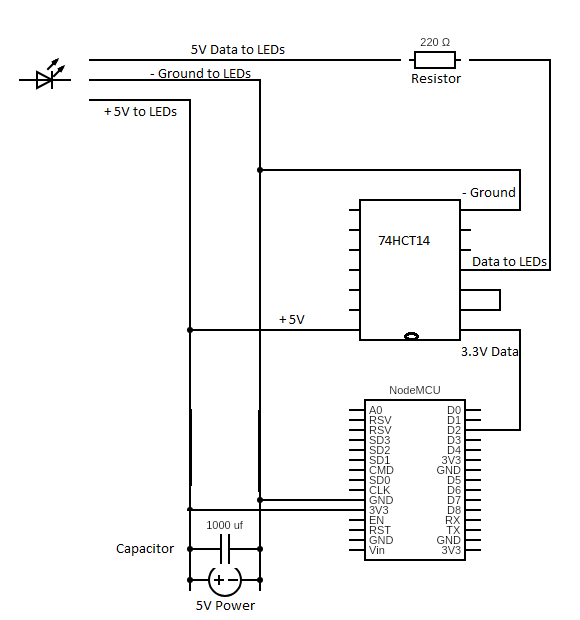
Drawn a quick diagram of what I currently have that may be working. Just would like your advice on proper wiring. 300 LEDs that are not all on at same time, roughly 30% max and no white. Now using 25W 5V 5A Mean Well - SGA40U05-P1J. Thank you.
Hi Mike, Sorry for not writing all the labels. I have completed it with labels and re-attached. Looking at your 74HCT14 diagram, I am not sure how it is wired as there are no pins like the part whereby it has 7 pins per side. The only indicator on the chip is a notch on one side indicating orientation and I have taken my best guess from the numbering and using the 74HCT14 datasheet to rewire based on your diagram. Please advise if I am correct in my interpretation(circuit(2).png). Thanks again for all your help!
I am not sure how it is wired as there are no pins like the part whereby it has 7 pins per side
What!
There are PIN numbers on every element of that chip.
It is a schematic, that means it is not designed to physically look like what you are making. Such a diagram is a called a physical layout diagram and is singularly useless trying time understand what is going on. Which is why we all hate Fritzing here.
Please advise if I am correct in my interpretation(circuit(2).png)
Well you haven’t labelled any of the pins on the 74HTC14, and have drawn the chip upside down. You have no ceramic 0.1uF capacitor across the power and ground of the chip, and you have left the unused gates in that chip unconnected.
You are trying to draw a hybrid between a schematic and physical layout diagram and getting the worst of both worlds.
You have not even labels what chip you have, I know because we are having this conversation but it would not help anyone work out what you are doing.
Hi Mike,
Yes, I agree that I am probably mixing up physical and schematic diagrams to which I apologize. I am trying to follow a physical layout diagram so that I can easily understand. In any image that I have found online using the 74HCT14 chip nothing is done with the remaining pins. When you say that "I have left the unused gates in the chip unconnected" does that mean that I have to connect them to each other as in 2A and 2Y, 3A and 3Y, etc.? I will add in the ceramic 0.1uF and change up my resistors as you have indicated.
Sorry for my lack of knowledge and I understand how it may be frustrating. I am like many others here that have found a new fascinating world with Arduino and around every corner there are new obstacles that require further learning and understanding. We appreciate forums like this and people such as yourself that share your knowledge. Thank you again for your help.
In any image that I have found online using the 74HCT14 chip nothing is done with the remaining pins.
That is because a lot of stuff on line is designed by idiots. I have over 50 years in this game. I wouldn’t tell you to do something if it is not necessary. You need to connect unused gates to add to the stability of the circuit. They are not doing anything else so what is the problem of treating them correctly?
When you say that "I have left the unused gates in the chip unconnected" does that mean that I have to connect them to each other as in 2A and 2Y, 3A and 3Y, etc.?
You can connect them in many ways, my circuit is just one of them. All the inputs to unused gates need to be connected to ground or another gates output.
change up my resistors as you have indicated.
That is the least important change, the resistor is there to act as a line matching impedance and as a protection if you apply a signal without having an power supply connected to the strip.
around every corner there are new obstacles that require further learning and understanding.
Yes, this attitude of “ electronics is just a matter of throwing together an circuit and hang trying to understand what is going on” is appalling. Hence all the crap you are finding on line. The most important advice I can give you is never believe anything you read on instructables unless you can spot the mistakes they have made.