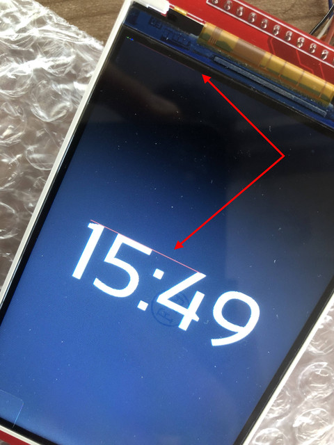
All code works, the only thing that doesn't work correctly is that when i combine the MFRC522 code together with the TFT display, i get those red stripes. Even than the RFID scanner works and i can write images or text to the display, i only get the strange stripes
As soon as i include this code the stripes appear:
I am not sure if this is more readable but maybe it is:
I posted the code, without that bit of code everything works fine (display shows everything correct).
The problem is in the code above.
I can post the code that writes the display:
spr.loadFont(FONT_SANSATION_REGULAR_100);
        spr.setTextColor(TFT_WHITE, TFT_BLACK);

        tft.setTextDatum(MC_DATUM);

        int xpos = tft.width() / 2;  // Centre of screen
        int ypos = tft.height() / 2;  // Centre of screen

        ClearDisplay();
        int font_width = spr.textWidth(current_time, 1) + 5;
        int font_height = spr.fontHeight(1);
        tft.setCursor(xpos - (font_width / 2), ypos - (font_height / 2));
        spr.printToSprite(current_time);
I know this bit works because it is exactly the same from the library example and like i said, when i remove the RFID code this shows correctly as well (without red stripe)
a quick look at the code you posted doesn't reveal any constructors.
Maybe the driver of one of the other parts uses the default SS for selecting its device, but you connected your TFT to SS. This might produce spurious writing to your TFT.
But if you don't follow advice that was given, we can't know or help.
david_prentice:
@ Paul__B ,
I could not read the wiring image in #3
It is too small.
The forum scales posted images to fit on the page along with the text and mostly does not use the full width of the window (on more current monitors such as a 22 inch, especially apparent if maximised). Zooming the page using Ctrl;+ expands the image, potentially to its full size and well beyond. The image in #3 is actually not much larger than you see it but zooming it allows most of it to be read - albeit with difficulty.
It does however contain a link to the image hosting page containing the full-size and perfectly clear original diagram, when you simply click on it.
When I post images, if (I know) they are actually larger than the space allocated on the forum page, I post them using image tags but also as a link to the same image. Due to a particularly nasty foul-up in the forum software, clicking on them as a link to an image causes the browser to refuse to display them natively, but refers you to the OS associated external image viewer such as IrfanView on Windoze or Document Viewer on Linux. However if they are actually of a greater resolution than allowed in the forum page, you can "zoom" them instead of using the link.
My apologies. When #3 was originally posted I tried "View image", clicking on image, ... all the usual tricks. With no success. The "view image" was very low resolution. I am sure that clicking did not work.
Anyway, now that I can see the whole schematic, there are a few anomalies. e.g. R1, R2 with capacitor symbols. C3, C4 with electrolytic on "output". 25AA02 chip with 5V power on a 3.3V system.
When there are obvious "features" in a schematic I would suspect multiple "software features" too.
I am not going to waste time speculating.
If someone posts buildable code, readers can reproduce the problem and offer a solution.
If a poster does not want to provide the information, she just has to solve it for herself.
I didn't change any of the messages so the link should have been there i think.
The 5v is from the development board. I need 5V on the eeprom (with 3.3V i don't get any values)
R1 and R2 are my bad, i used the same symbol because i use the same size pcb smd components. I will look for the right symbols.
I will post my code tomorrow, i have made seperate .h files for parts of the code so i need to find a good way to make it available here
All the help is welcome, if you have a better solution for the 5.0V for the 25AA03E48 that would be great.
I have also noticed that i get different MAC addresses over time, isn't that wrong?
The problem is if i connect it to 3.3V i get only 0 values.
Do you know what can be wrong?
Thanks for the help so far and if you need more information please let me know
Your ZIP is on an external server with a password. Unlikely for readers to trust.
When downloaded into a Project directory, there is executable code in H files.
There are an inordinate number of external libraries to install. Several that are not available through the IDE Library Manager.
I wasted some time attempting to build your "project".
I am out.
David.
p.s. I would be interested in investigating your "red line" problem.
Bodmer would be probably be interested too.
If you can provide a minimal buildable example, you might get some response.
The Arduino system means that everyone has the "core" set of libraries and examples that come with the IDE.
Everyone can access any "approved" third party libraries via the IDE Library Manager.
So you can paste a sketch or attach a project ZIP to the Forum.
And anyone in the world can replicate your project.
Yes, you can flout the C / C++ conventions if you want. e.g. code in H files
But you will keep people happier if you just create a minimal example that exhibits your problem.
Or at least add any "unusual files" to local tabs in your project.
Build your project yourself first. All the libraries, versions and locations are reported in a "verbose compile".
You just need to go through the list in the Library Manager.
David.
p.s. we make allowances for young members, newcomers, non-English speakers, ...
I am guessing that you don't fall into those categories.