Hello,
Perhaps someone can advice how to properly handle the case on Arduino Due when I need to generate Burst PWM signal relative to the master signal. For ex there is master channel with frequency 100 KHz and I need to generate 5 impulse of 1MHz in the certain phase of the master signal. Burst itself can be done easely thru the PWM_Handler by counting the number of interrupts but the issue is that it is not possible to do a phase shift of this signal. Another way I wought to use Timers and run the timer with the certain period that will correspond to the phase shift time. But looks like it is not reliable way since Burst signal starts floating in the time.
I would appreaciate for any clarification or feedback if it is even possible to do on Due.
Your description is unclear to me.
Could you draw and post one above the other(s) and for 1 or 2 periods, firstly the "Master" PWM pulse with its frequency and duty cycle, and the other(s) PWM signal(s) with its(their) frequency, duty cycle and phase shift relative to the "Master" PWM pulse.
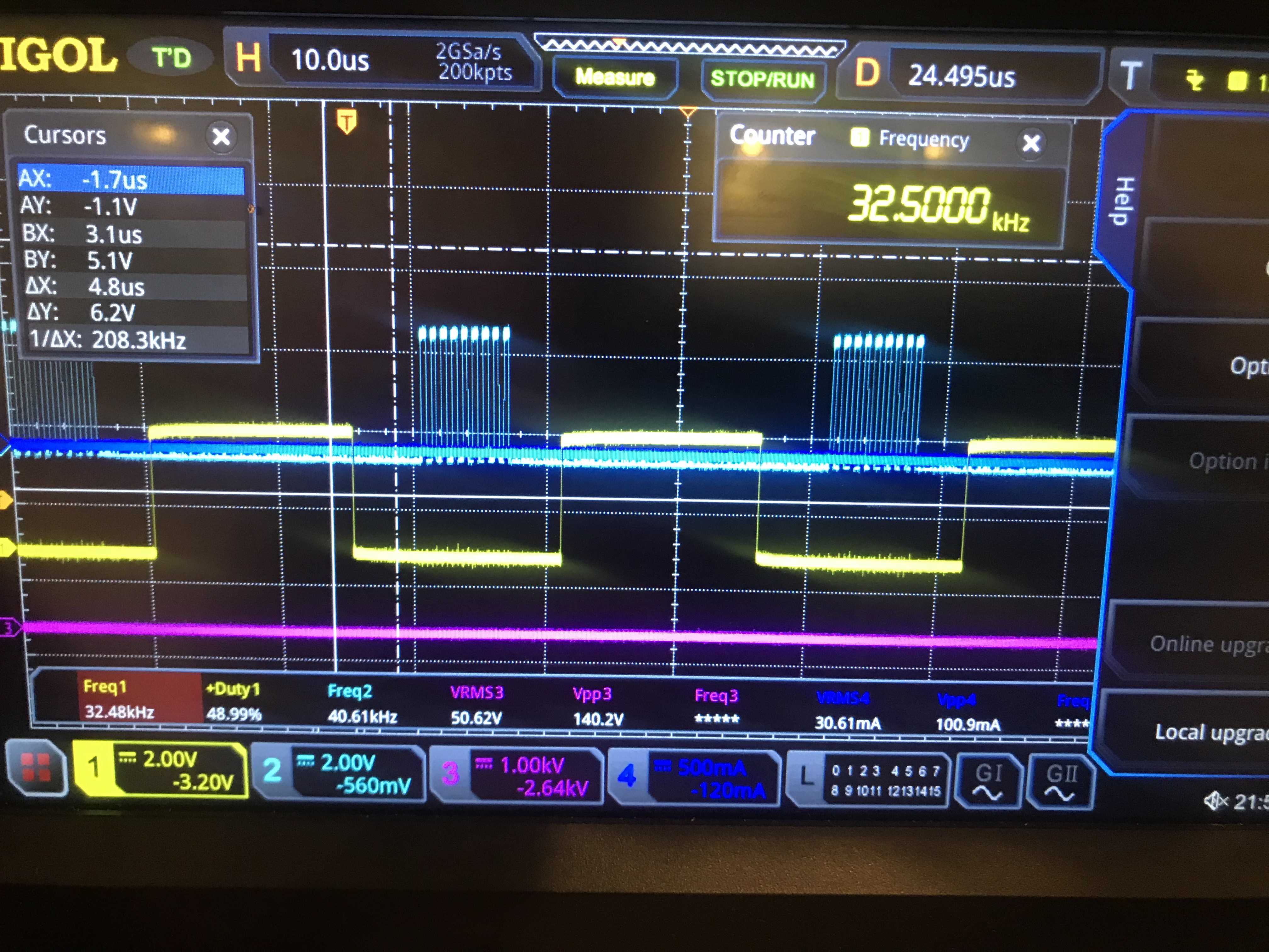
Thank you for the quick response. I would like to achieve the below signal: IMG_6291.jpg, IMG_6292.jpg
Main freq is 32khz, burst freq is 1.3Mhz. I can specify the number of impulses, burst freq and duty and phase shift of burst signal relative to the 32khz signal. I would like to achieve the same on Due if it is possble.
IMO the easiest way to achieve this is to use PWM_CMPVx, PWM_CMPMx and PWM_IER2 registers. These registers are intended to generate software interrupts (See Sam3x datasheet pages 993, 1003, 1019, 1040,...)
Let's say PWM channel 0 is your "Main" PWM frequency programed at 32 KHz with a 50% duty cycle.
Let's say PWM channels 1 and 2 are PWM pulses at 1.3 MHz (BTW 84 MHz/1.3 MHz is not an integer) with a 50% duty cycle.
You will be using e.g. PWM_CMPV0 and PWM_CMPV1 to compare PWM channel 0 internal counter with 2 values: The ones corresponding to start and stop of the desired "output" PWM of Image 1 (you are using PWM channel 1 for that).
Likewise, PWM_CMPV2 and PWM_CMPV3 to compare PWM channel 0 internal counter with stop and start of the desired "output" PWM of Image 2 (you are using PWM channel 2 for that).
Inside PWM handler, test which comparison triggered the interrupt and accordingly enable/disable PWM channel 1 or 2 with PWM_ENA / PWM_DIS.
Here is an example sketch to get started with PWM registers programing (The builtin LED blinks with an 1 Hz frequency):
/*********************************************/
/*          PWMH0 641  Hz                    */
/*********************************************/
void setup() {
  pinMode(LED_BUILTIN, OUTPUT);

  PMC->PMC_PCER1 |= PMC_PCER1_PID36;                   // PWM power ON

  PIOC->PIO_PDR |= PIO_PDR_P3;                         // Set PWM pin to a peripheral
  PIOC->PIO_ABSR |= PIO_PC3B_PWMH0;                    // Set PWM pin peripheral type B for PWMH0 (Arduino pin 35)

  PWM->PWM_CLK = PWM_CLK_PREB(0) | PWM_CLK_DIVB(2);    // select Frequency for clock B: Mck/2 = 42 MHz
  PWM->PWM_CH_NUM[0].PWM_CMR = PWM_CMR_CPRE_CLKB;      // The period is left aligned, clock source as CLKB on channel 0
  PWM->PWM_CH_NUM[0].PWM_CPRD = 65535;                 // Set the PWM frequency 42 MHz/PWM_CPRD = 641 Hz
  PWM->PWM_CH_NUM[0].PWM_CDTY = 32768;                 // Set the PWM duty cycle = (CPRD/CDTY) * 100 %

  PWM->PWM_IER1 = PWM_IER1_CHID0;                      // Interrupt on PWM Channel 0 counter
  NVIC_EnableIRQ(PWM_IRQn);                            // Enable interrupt

  PWM->PWM_ENA = PWM_ENA_CHID0;                        // Enable PWM channel 0
}

void loop() {
  // update PWM frequency with  PWM->PWM_CH_NUM[0].PWM_CPRDUPD = ....;
  // update PWM duty cycle with PWM->PWM_CH_NUM[0].PWM_CDTYUPD = ....;
}

void PWM_Handler() {
  static uint32_t Count;

  PWM->PWM_ISR1;      // Clear status register
  if (Count++ == 641)
  {
    PIOB->PIO_ODSR ^= PIO_ODSR_P27;
    Count = 0;
  }
}
Thank you ard_newbie.
I've tried with PWM_IER2 but it is not triggered. I moved to PWM_IER1 and the interruption is triggered, but 2nd channel does not interrupt. I would like to produce burst at certain phase of channel 3 and turn off the bursts after certain number of impulses. The code is below:
volatile uint32_t counter = 0, burst = 4;
volatile uint32_t burst_frequency = 400;// Set the PWM burst_frequency
volatile uint32_t push_pull_frequency = 4000;
volatile uint32_t push_pull_duty = push_pull_frequency / 2;
volatile uint32_t dead_time = push_pull_duty / 2;


void setup()
{

  // PWM Set-up burst on pin: DAC1
  REG_PMC_PCER1 |= PMC_PCER1_PID36;                               // Enable PWM
  REG_PIOB_ABSR |= PIO_PDR_P16 ;                                  // Set PWM pin perhipheral type A or B, in this case B
  REG_PIOB_PDR  |= PIO_PDR_P16 ;                                  // Set PWM pin to an output
  REG_PWM_CLK = PWM_CLK_PREA(0) | PWM_CLK_DIVA(1);                // Set the PWM clock rate to 84MHz (84MHz/1)
  PWM->PWM_CH_NUM[0].PWM_CMR = PWM_CMR_DTE | PWM_CMR_CPRE_CLKA;   // Enable single slope PWM and set the clock source as CLKA
  PWM->PWM_CH_NUM[0].PWM_CPRD = burst_frequency;                  // Set the PWM burst_frequency 84MHz/40kHz = 2100
  PWM->PWM_CH_NUM[0].PWM_CDTY = 0;                                // Set the PWM duty cycle 0%
  //NVIC_SetPriority(PWM_IRQn, 0);                                // Set the Nested Vector Interrupt Controller (NVIC) priority for the PWM controller to 0 (highest)
  //NVIC_EnableIRQ(PWM_IRQn);                                     // Connect PWM Controller to Nested Vector Interrupt Controller (NVIC)
  PWM->PWM_IER1 |= PWM_IER1_CHID0;                                // Enable interrupt on PWM channel 0 triggered at end of PWM period
  PWM->PWM_ENA  |= PWM_ENA_CHID0;                                 // Enable the PWM channel

  // PWM set-up on digital pins D40 (PWML3) and D41 (PWMH3)
  PIOC->PIO_ABSR |= PIO_ABSR_P9 | PIO_ABSR_P8;                                  // Set the port C PWM pins to peripheral type B
  PIOC->PIO_PDR |=  PIO_PDR_P9 | PIO_PDR_P8;                                    // Set the port C PWM pins to outputs
  PWM->PWM_CH_NUM[3].PWM_CPRD = push_pull_frequency;                            // Set the PWM burst_frequency
  PWM->PWM_CH_NUM[3].PWM_CMR = PWM_CMR_DTE | PWM_CMR_CPRE_CLKA;                 // Enable single slope PWM and set the clock source as CLKA
  PWM->PWM_CH_NUM[3].PWM_DT = PWM_DT_DTH(dead_time) | PWM_DT_DTL(dead_time);    // Set the dead-time for a 2.5us delay on both outputs
  PWM->PWM_CH_NUM[3].PWM_CDTY = push_pull_duty;                                 // Set the PWM duty cycle to 50%
  NVIC_SetPriority(PWM_IRQn, 0);                                                // Set the Nested Vector Interrupt Controller (NVIC) priority for the PWM controller to 0 (highest)
  NVIC_EnableIRQ(PWM_IRQn);                                                     // Connect PWM Controller to Nested Vector Interrupt Controller (NVIC)
  PWM->PWM_CMP[3].PWM_CMPV = PWM_CMPV_CV(push_pull_frequency/2);                //Set comparison value
  PWM->PWM_CMP[3].PWM_CMPM = PWM_CMPM_CEN;                                      //enable comparison x
  PWM->PWM_IER1 |= PWM_IER1_CHID3;                                              // Enable interrupt on PWM channel 0 triggered at end of PWM period
  PWM->PWM_ENA |= PWM_ENA_CHID3;                                                // Enable PWM channel


  //REG_PWM_SCM |= PWM_SCM_SYNC0 | PWM_SCM_SYNC3;            // Set the PWM channels as synchronous

  //Timer1.attachInterrupt(timer_pwm).setFrequency(0.5).start();

  //action_tc1.start(push_pull_frequency,timer_pwm,&action_ctx1);
}

void loop() {
  // Output a burst of 8 PWM pulses every second

  Serial.begin(9600);
  Serial.println("Loop");
  delay(1000);                      // Wait 100ms
  //PWM->PWM_DIS |= PWM_DIS_CHID0;     // Disable PWM channel
  PWM->PWM_CH_NUM[0].PWM_CDTYUPD = 0;   // Set the PWM duty cycle to 0%
  PWM->PWM_CH_NUM[0].PWM_CDTY = 0;   // Set the PWM duty cycle to 0%
  REG_PWM_IDR1 |= PWM_IDR1_CHID0;    // Disable interrupts
  PWM->PWM_DIS |= PWM_DIS_CHID0;     // Disable PWM channel
  counter = 0;
}

void PWM_Handler() {
  if (REG_PWM_ISR1 & PWM_ISR1_CHID3)    // Check if an update condition has occured
  {
    //action_tc1.start(push_pull_frequency/4,timer_pwm,&action_ctx1);
    timer_pwm();
  }
  else if (REG_PWM_ISR1 & PWM_ISR1_CHID0)    // Check if an update condition has occured
  {

    if (counter == 0)
    {
      counter++;
      REG_PWM_CDTYUPD0 = burst_frequency / 2;          // Set the PWM duty cycle 50%
    }
    else if (counter < burst)                    // Have we counted up?
    {
      counter++;                        // Increment the counter and continue
    }
    else
    {
      /*
      PWM->PWM_DIS |= PWM_DIS_CHID0;     // Disable PWM channel
      PWM->PWM_CH_NUM[0].PWM_CDTY = 0;   // Set the PWM duty cycle to 0%
      REG_PWM_IDR1 |= PWM_IDR1_CHID0;    // Disable interrupts
      REG_PWM_CDTYUPD0 = 0;
      counter = 0;
      //action_tc1.stop();
      */
    }
  }
}

void timer_pwm()
{
  counter = 0;
  PWM->PWM_ENA  |= PWM_ENA_CHID0;                                 // Enable the PWM channel
  PWM->PWM_IER1 |= PWM_IER1_CHID0;    // Enable event interrupts
  PWM->PWM_CH_NUM[0].PWM_CDTY = burst_frequency / 2;


}